Eureka AIR delivers breakthrough ideas for toughest innovation challenges, trusted by R&D personnel around the world.

Exhaust heat exchanger

Inactive Publication Date: 2005-01-13
MODINE MFG CO
View PDF11 Cites 8 Cited by
  • Summary
  • Abstract
  • Description
  • Claims
  • Application Information

AI Technical Summary

Problems solved by technology

The entire system (i.e., the vehicle with its internal combustion engine) and an overall significantly reduced energy balance is naturally at issue.
These exhaust heat exchangers do not appear to be particularly compact, which is of particular importance in the limited engine compartment space of motor vehicles.

Method used


Image

  • Exhaust heat exchanger
  • Exhaust heat exchanger
  • Exhaust heat exchanger

Examples


Embodiment Construction

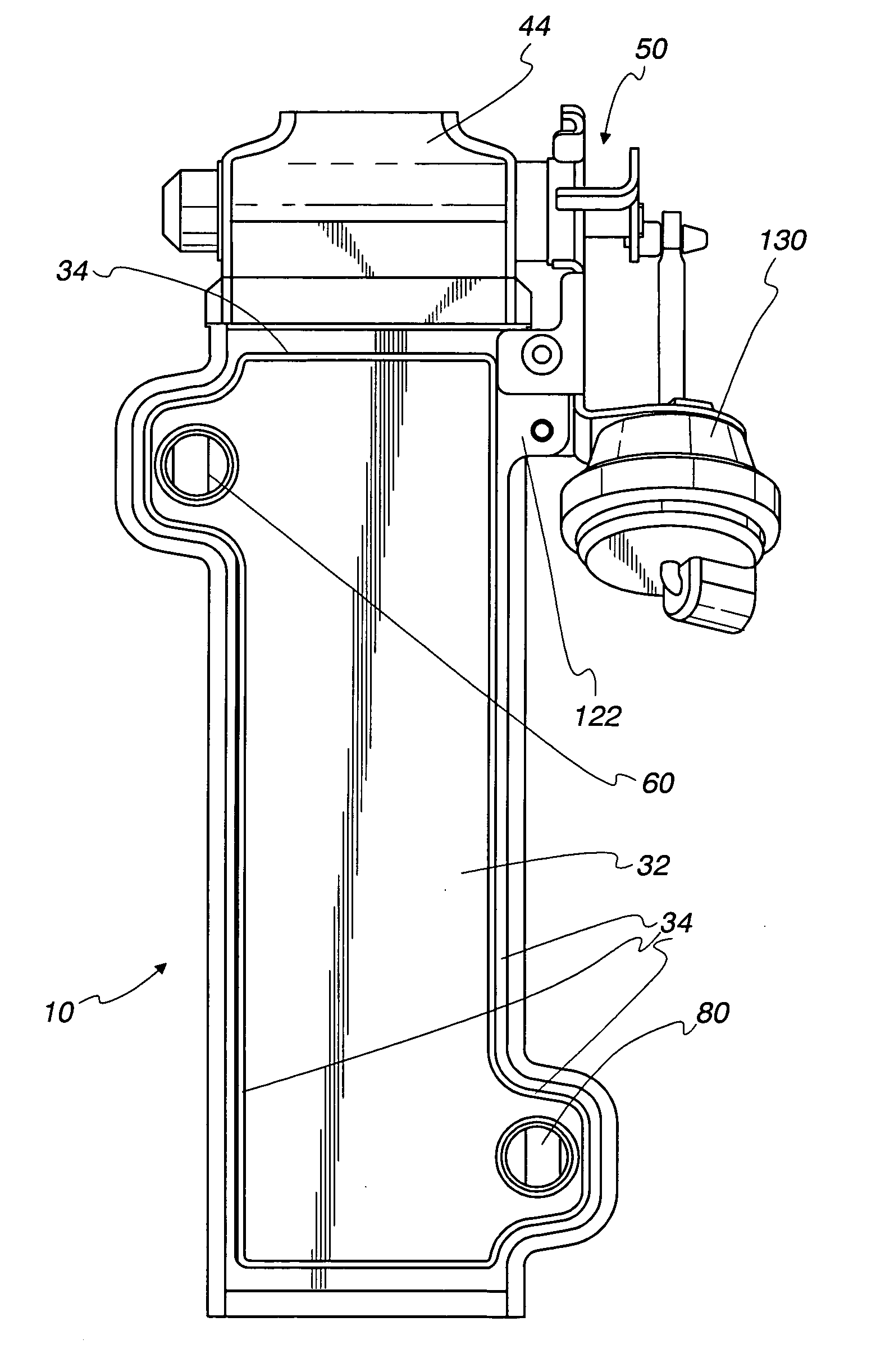
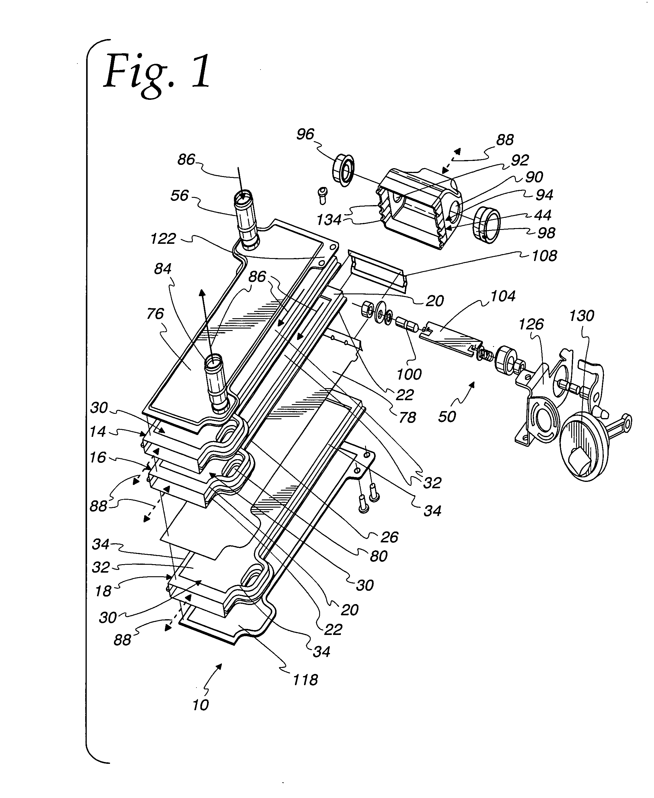
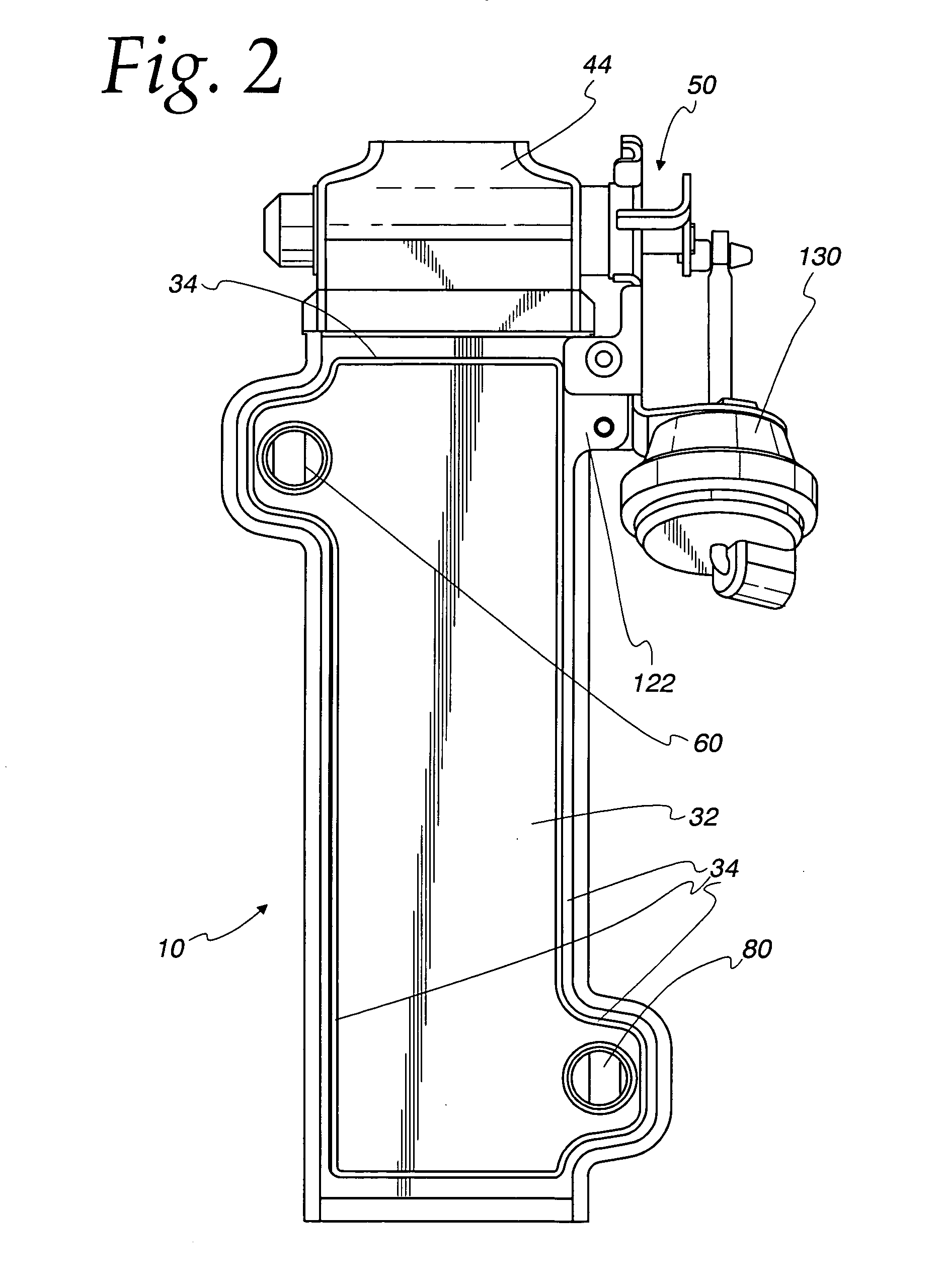
[0031] A housingless exhaust heat exchanger 10 embodying to the present invention is variously shown in the Figures. In the illustrated exemplary embodiment, the heat exchanger 10 is for use with a vehicle cooled by the coolant (preferably liquid) of the internal combustion engine.

[0032] In the illustrated embodiment, the heat exchanger 10 includes three flat tubes 14, 16, 18, each of which is advantageously formed of a pair of deformed plates 20, 22 suitably joined along their generally longitudinal edges 26. The plates 20, 22 also have a peripheral contoured section 30 with a recessed face 32 surrounded by a peripheral lip 34, such as described in EP 992 756 B1, the disclosure of which is hereby fully incorporated by reference. EP Application 03 007 724.2 (EP Publication 1 376 043 A2) also discloses features of a housingless heat exchanger which may be used with the present invention, the disclosure of which is hereby also fully incorporated by reference.

[0033] The flat tubes 14...


PUM


Abstract

A housingless heat exchanger including a stack of flat tubes with at least two being cooling tubes and at least one being a bypass tube. Collecting tanks are on the tube ends and diffuse gas streaming in the tube flow paths. The flat tubes each comprise a connected pair of plates defining a flow path, and an enclosed space is defined between adjacent flat tubes. Coolant inlet and outlet channels are formed by connected plate openings connect to the enclosed space between the cooling tubes whereby coolant flows through that enclosed space. A switching valve in one collecting tank is movable between a cooling position in which the gas streams through the cooling tubes and a bypass position in which the gas streams through the bypass tube. A closure in the coolant inlet and outlet channels blocks coolant from adjacent the bypass tube. An insulating plate may also, or alternatively, be between the bypass tube and the cooling tube adjacent the bypass tube to block heat exchange between coolant and the bypass tube.

Description

CROSS REFERENCE TO RELATED APPLICATION(S) [0001] Not applicable. STATEMENT REGARDING FEDERALLY SPONSORED RESEARCH OR DEVELOPMENT [0002] Not applicable. REFERENCE TO A MICROFICHE APPENDIX [0003] Not applicable. TECHNICAL FIELD [0004] The present invention is directed toward heat exchangers, and particularly toward exhaust heat exchangers usable in vehicles. BACKGROUND OF THE INVENTION AND TECHNICAL PROBLEMS POSED BY THE PRIOR ART [0005] Exhaust heat exchangers may be advantageously used, for example, to cool exhaust gas, allowing it to be recirculated for emission reduction in vehicles. The recirculated exhaust must be cooled in order to achieve high efficiency during recirculation, especially to achieve better degrees of filling. The entire system (i.e., the vehicle with its internal combustion engine) and an overall significantly reduced energy balance is naturally at issue. [0006] For many years, however, all the operating situations in the vehicle have been analyzed and measures ...

Claims


Application Information

Patent Timeline
IPC IPC(8): F02M25/07F28D9/00F28F27/02
CPCF01N2240/02F02M25/0727F02M25/0729F02M25/0731Y02T10/121F28D21/0003F28F27/02F28F2250/06F28D9/0043F28F2250/104F02M26/23F02M26/26F02M26/28
Inventor BROST, VIKTORSTRAHLE, ROLANDECKERT, THOMAS
Owner MODINE MFG CO
Why Eureka
Eureka Blog
Learn More