Frit material and bonding method for microfluidic separation devices

a technology of microfluidic separation and frit material, which is applied in the direction of positive displacement liquid engine, filter regeneration, ultrafiltration, etc., can solve the problems of difficult bonding of conventional frit materials to the polymer layers of stacked layer devices, the thickness of conventional hplc frit materials cannot be used within laminated multi-layer microfluidic separation devices, and the inability to manufacture microfluidic devices with integral hplc columns

Inactive Publication Date: 2005-01-13
AGILENT TECH INC
View PDF45 Cites 18 Cited by
  • Summary
  • Abstract
  • Description
  • Claims
  • Application Information

AI Technical Summary

Problems solved by technology

One difficulty in fabricating microfluidic devices having integral HPLC columns, however, has been including frits within such devices.
Because multi-layer multifluidic devices typically use device layer materials having thicknesses ranging from about one mil (twenty-five microns) to about twenty-five mils (635 microns), conventional HPLC frit materials are too thick to be used within a laminated multi-layer microfluidic separation device.
Moreover, certain conventional frit materials, such as stainless steel, may be difficult to bond to the polymer layers of a stacked layer device.
In fact, conventional polymer frit materials also may be difficult to bond to other polymers, particularly where it is desirable to avoid the use of adhesives that could contaminate a microfluidic device.
However, it has been found that when frits are composed of material closely related to the material of the surrounding device layers, the temperature required to achieve the desired bonding tends to melt the frit to the degree that it is rendered inoperable or its effectiveness is reduced.
When dissimilar materials are used, with desirable melting point differentials, device layer materials and frit materials bond less effectively, frequently resulting in undesirable separation of the layers from the frits at operational pressures.
The polycarbonate frit presented several issues related to the fabrication and operation of the assembled device.
Devices made with the polycarbonate frit suffered from a lack of reproducible pressure drop, which was believed to be caused by the clogging or blocking of the pores of the frit with the stationary phase material.
As a result, the bonding between the polycarbonate frit and the surrounding polymeric film was relatively weak, occasionally permitting undesirable fluid flow around the frit.
However, even when multiple discrete frits are used, there may be some wicking of fluid between each discrete frit and the surrounding device layers.

Method used


Image

  • Frit material and bonding method for microfluidic separation devices
  • Frit material and bonding method for microfluidic separation devices
  • Frit material and bonding method for microfluidic separation devices

Examples


Embodiment Construction

[0022] Definitions

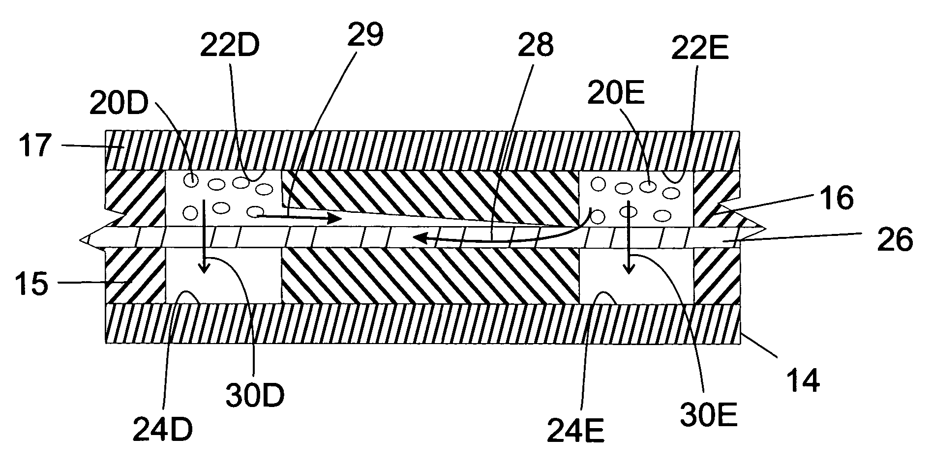
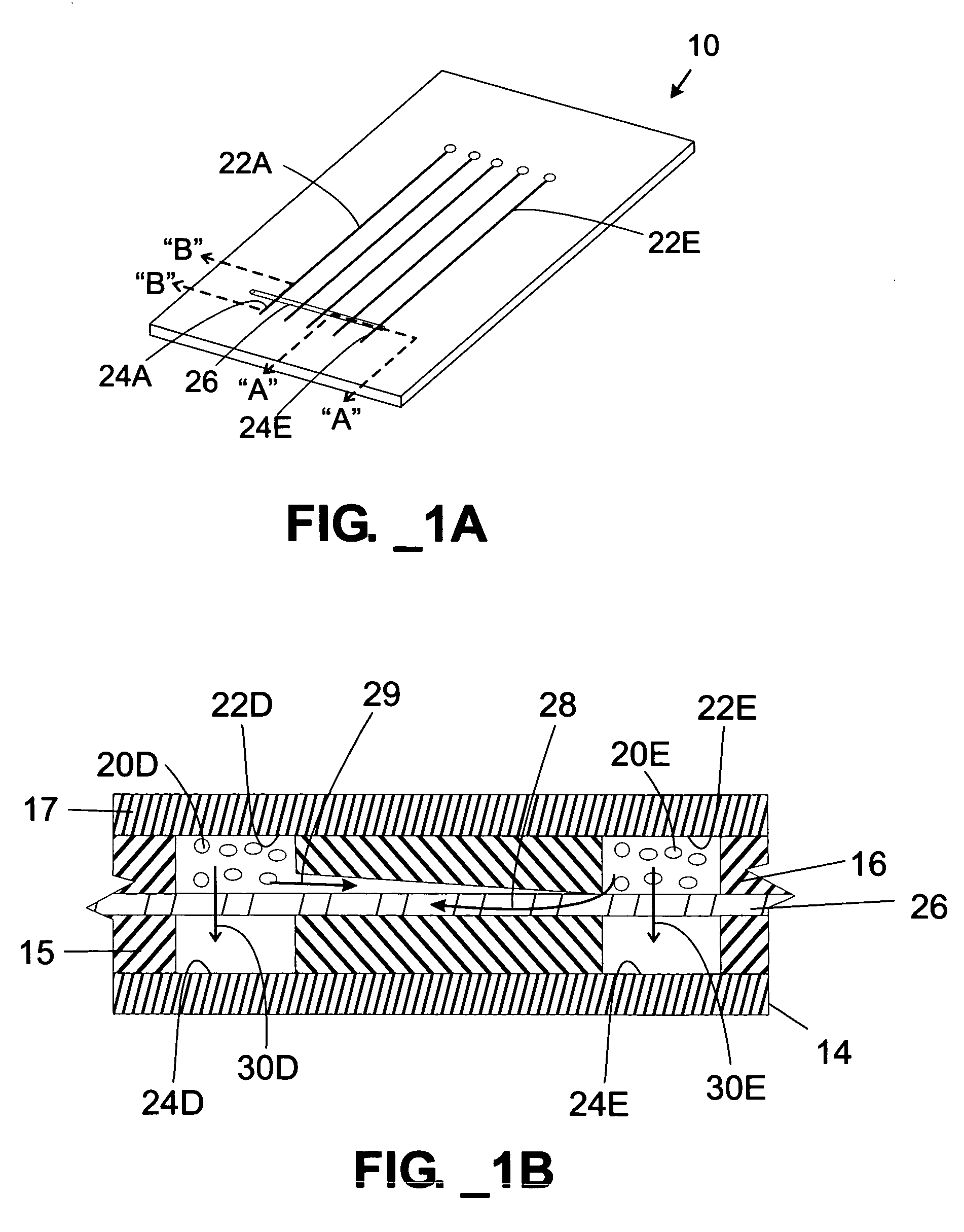
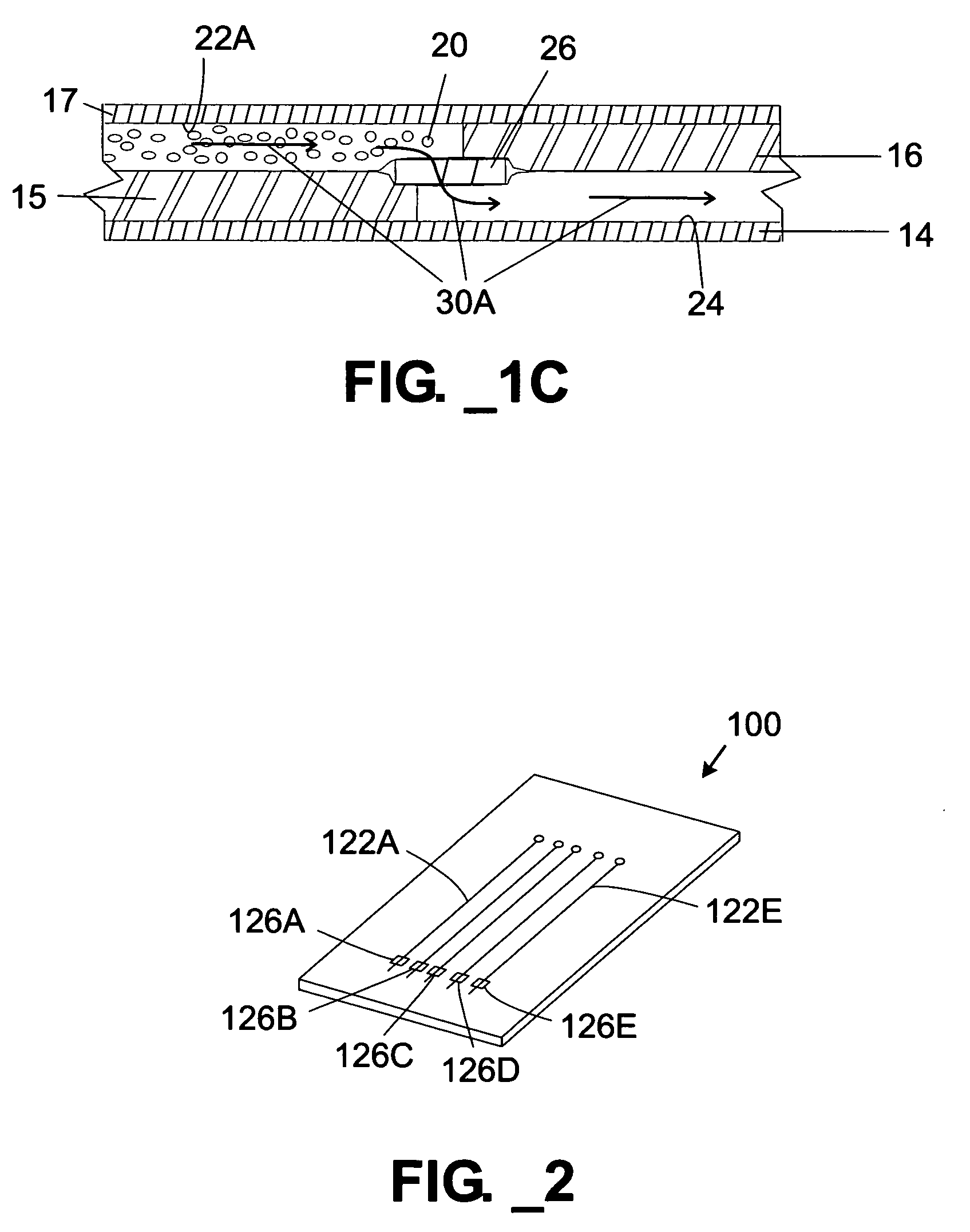
[0023] The terms “channel” or “chamber” as used herein are to be interpreted in a broad sense. Thus, they are not intended to be restricted to elongated configurations where the transverse or longitudinal dimension greatly exceeds the diameter or cross-sectional dimension. Rather, such terms are meant to comprise cavities or tunnels of any desired shape or configuration through which liquids may be directed. Such a fluid cavity may, for example, comprise a flow-through cell where fluid is to be continually passed or, alternatively, a chamber for holding a specified, discrete ratio of fluid for a specified ratio of time. “Channels” and “chambers” may be filled or may contain internal structures comprising, for example, valves, filters, and similar or equivalent components and materials.

[0024] The term ‘rit’ as used herein refers to a microporous material used to retain stationary phase material within a separation column for performing pressure-driven liquid chrom...


PUM

PropertyMeasurementUnit
operating pressureaaaaaaaaaa

Abstract

A multi-layer microfluidic separation device comprises a polymeric membrane frit that may be securely bonded within the device and minimizes lateral wicking. Stationary phase material having an average particle size is retained by a frit having an average pore size that is smaller than the average particle size. In one embodiment, a secure bond is ensured by treating the polymer to match its surface energy to that of the materials to which it is bound. Treatments include plasma treatment, irradiation and the application of acids.

Description

STATEMENT OF RELATED APPLICATION(S) [0001] This application claims priority to U.S. patent application Ser. No. 10 / 256,505, filed Sep. 27, 2002, and to U.S. Provisional Patent Ser. Nos. 60 / 393,953 and 60 / 357,683, filed Jul. 2, 2002 and Feb. 13, 2002, respectively.FIELD OF THE INVENTION [0002] The present invention relates to microfluidic devices employing frit materials. BACKGROUND OF THE INVENTION [0003] Chemical and biological separations are routinely performed in various industrial and academic settings to determine the presence and / or quantity of individual species in complex sample mixtures. There exist various techniques for performing such separations. One separation technique, liquid chromatography, encompasses a number of methods that are used for separating closely related components of mixtures. Liquid chromatography is a physical method of separation involving a sample (or sample extract) being dissolved in a mobile phase (which may be a gas, a liquid, or a supercritica...

Claims


Application Information

Patent Timeline
Patent Type & Authority Applications(United States)
IPC IPC(8): B01D61/18B01D61/20B01D63/08B01D65/00B01F13/00B01J19/00B01L3/00B29C35/08B29C59/14B29C59/16B29C65/00B29C65/18B32B38/00B32B38/10G01N27/447G01N30/56G01N30/60
CPCB81B2201/058B29C66/727G01N27/44791G01N30/6095G01N2030/565G01N2030/6056B81C3/008B29C66/81812B29C66/929B01D63/088B01D61/18B01D61/20B01D63/081B01D63/087B01D65/003B01F13/0059B01F15/0264B01J19/0093B01L3/502707B01L3/502753B01L2200/10B01L2200/12B01L2300/0681B01L2300/0864B01L2300/0867B01L2300/0874B01L2300/0887B01L2300/14B01L2400/0406B01L2400/0688B29C59/14B29C59/16B29C65/18B29C66/02B29C66/026B29C66/45B29C66/92441B29C2035/0827B29K2023/00B29K2023/06B29K2023/12B29K2071/00B29L2031/756B32B38/0008B32B38/10B32B2037/0092B32B2309/02B32B2309/12B29C66/9241B29C65/00B29C66/73161B29C66/71B29C66/1122B01F33/30B01F35/7182
Inventor KOEHLER, JEFFREY A.PATEL, PAREN P.
Owner AGILENT TECH INC
Why Eureka
Try Eureka