Method for friction stir welding

a friction stir and welding technology, applied in the direction of high frequency current welding apparatus, non-electric welding apparatus, manufacturing tools, etc., can solve the problems of reducing the tendency of softened metal to adhere to the rotating probe and tool shoulder, probably the greatest obstacle to achieving good welding, and reducing the tendency of softened metal to adhere to the rotating probe and shoulder of the tool

Inactive Publication Date: 2005-01-13
ANDERSSON CLAES GORAN +1
View PDF2 Cites 39 Cited by
  • Summary
  • Abstract
  • Description
  • Claims
  • Application Information

AI Technical Summary

Benefits of technology

[0017] The object of the invention is to keep the temperature of the tool probe (once stable welding conditions have been achieved within a given range in order to enable consistent weld quality by not overheating or overcooling the weld zone.

Problems solved by technology

Generally one may say that within the welding technique the thickness of the metal / alloy to be joined presents probably the greatest obstacle to achieving a good weld.
Further, the problem of evolved heat has been disclosed in EP-A2-0,810,056 (mentioned above), in connection with the welding of aluminum where the problem encountered was that the weld produced needed machining on account of the resulting weld being rough.
It was recognized that cooling of the tool, when welding materials that are difficult to weld, such as aluminum alloys (essentially non-extrudable) during the welding process, reduces the tendency of the softened metal to adhere to the rotating probe and shoulder of the tool, thus giving a smother surface.
For welding thicker plates of 15 mm up to 25 mm in a single pass, the thickness varying between 15 to 25 mm probes of the type having a 1:1 length / diameter could be used, however these probes tend to displace an excessive amount of material.
As the plates grow thicker scaled-up probes of known type will displace increasing amounts of material and trials have shown that this is not a recommended way of solving the problem.
However, the welding of thicker materials will necessitate a higher input of pressure put on the probe indicating that it may be a problem to lengthen the probe without making it wider.
The problem seems to be that during the plunge sequence most of the heat generated is rapidly conducted through the bulk of the welded material, e.g. copper, and the tool might lock and then be sheared off.
However increasing the rotation speed above 400 rev / min rapidly increases the temperature of the top surface of the work pieces causing that to become extremely soft before the underlying welded material, e.g. copper becomes sufficiently soften to for welding to take place.
This situation may cause the shoulder of the tool to penetrate or plunge over an excessive distance into the softened top surface layer.

Method used


Image

  • Method for friction stir welding
  • Method for friction stir welding
  • Method for friction stir welding

Examples


Embodiment Construction

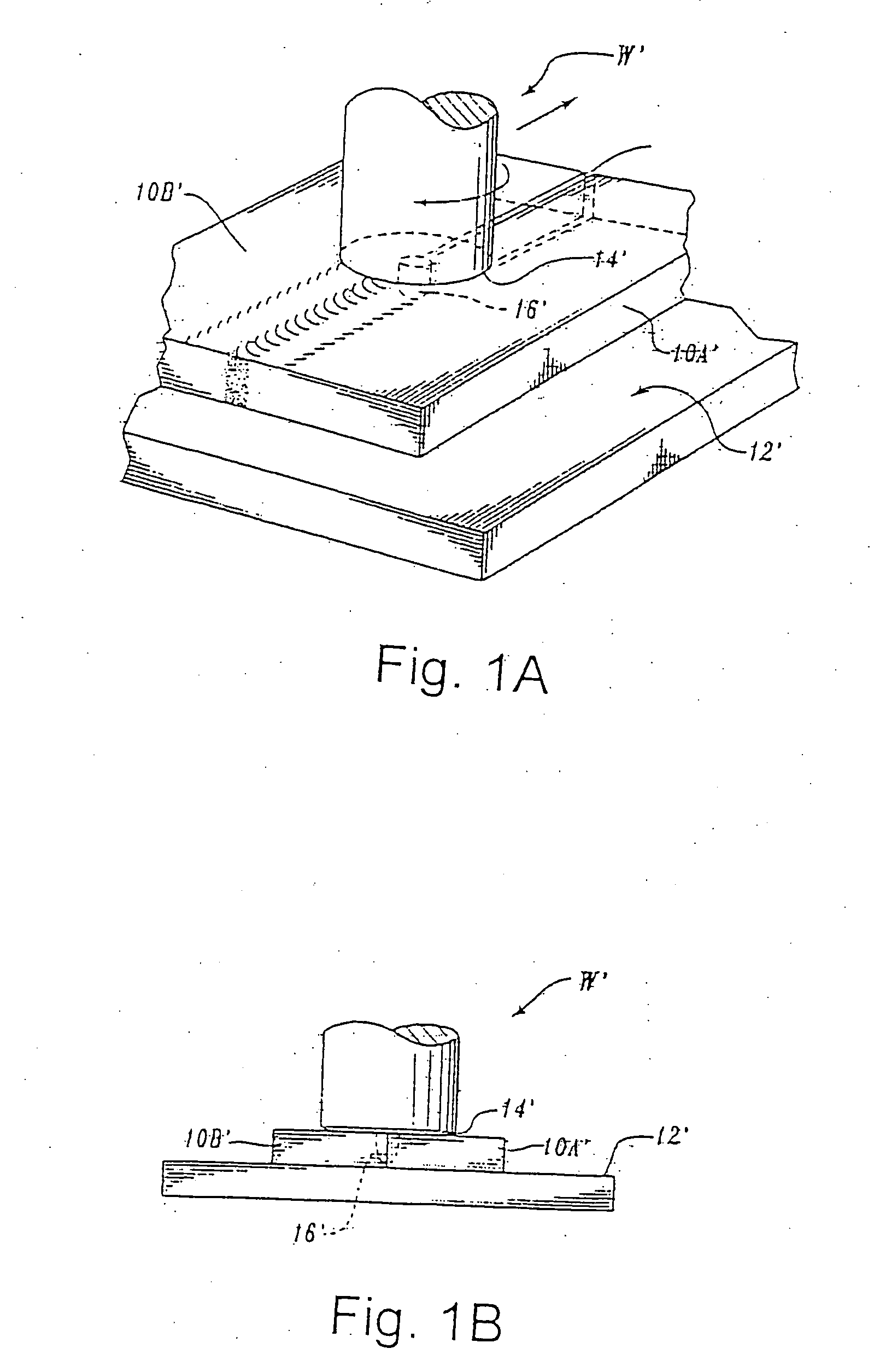
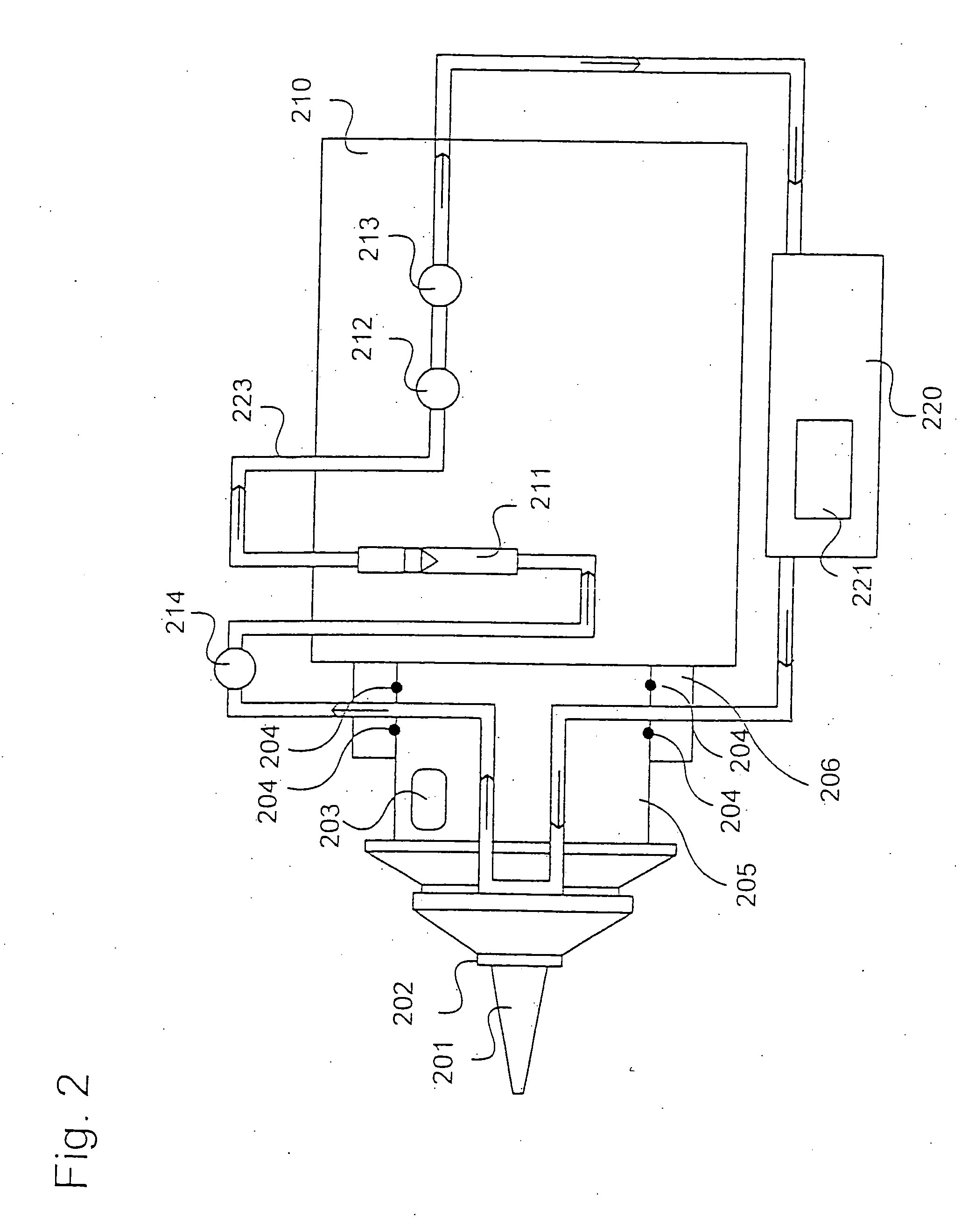
[0030] In accordance with the invention excess heat is removed from a stir welding tool in order to achieve an improved weld structure throughout the whole weld. In accordance with the invention an embodiment of a temperature control arrangement for a friction stir welding tool and process is described. In the drawing, shown in FIG. 2, a friction stir welding probe 201 and the shoulder 202 thereof is shown mounted on a tool body 210.

[0031] In this drawing is also indicated that the friction stir welding tool has one non-rotating part 206, 210 and a rotating part 205, 202, and 201.

[0032] A temperature control arrangement is shown. Within the tool body 210 and in contact with the tool shoulder a tool temperature controlling circuit 223 is shown. The conduit passes through both the rotating and the non-rotating parts of the friction stir welding tool. In order to accomplish this rotating seals 204 are arranged at the interface between the two parts.

[0033] A chilling unit 220 is arra...


PUM

PropertyMeasurementUnit
lengthaaaaaaaaaa
lengthaaaaaaaaaa
thicknessaaaaaaaaaa

Abstract

The invention relates to a method of friction stir welding in which use is made of a rotating friction stir welding tool, said tool having a probe, the method comprises, (a) temperature control of the tool during welding of a workpiece of hard to weld materials by passing a temperature controlling coolant through one or more channels in the tool in order to control the temperature of the probe, thereby removing excessive heat from the tool and from the area of the workpiece being welded, (b) said coolant having a predetermined first temperature upon entering the tool, (c) measuring a second predetermined temperature indicative of the tool probe temperature, and (d) controlling the welding process such that the tool probe is kept essentially at a predetermined tool probe temperature. The invention also relates to a combination for performing the method.

Description

FIELD OF THE INVENTION [0001] The present invention relates to a method of friction stir welding using temperature control, and a friction stir welding probe with a temperature controlling arrangement. REFERENCE TO RELATED APPLICATION [0002] Reference is hereby made to commonly assigned, co-pending application 0101663-3, filed in which an improved friction stir welding probe is described, and which is incorporated here by reference. BACKGROUND OF THE INVENTION [0003] Friction stir welding represents a relatively new welding technique. The technique has been developed welding metals and alloys which have been difficult to weld on account of e.g. thickness of the metal / alloy to be joined or simply metal / alloys that have been difficult to weld due to the need of special shielding gases and specially in thick material the need to eliminate voids and / or solidification cracking defects as the weld cools down. [0004] Generally one may say that within the welding technique the thickness of ...

Claims


Application Information

Patent Timeline
Patent Type & Authority Applications(United States)
IPC IPC(8): B23K13/02B23K20/12
CPCB23K20/1245B23K20/1235B23K20/12
Inventor ANDERSSON, CLAES-GORANANDREWS, R.E.
Owner ANDERSSON CLAES GORAN
Why Eureka
Try Eureka