
High-pressure discharge lamp and method of manufacturing high-pressure discharge lamp

a technology of discharge lamp and discharge lamp, which is applied in the manufacture of electric discharge tube/lamp, cold cathode, and electric discharge system. it can solve the problems of lowering the luminance of the discharge lamp, rupturing the lamp bulb, and gas leakage from the lamp bulb

Inactive Publication Date: 2005-01-13
USHIO DENKI KK
View PDF7 Cites 5 Cited by
  • Summary
  • Abstract
  • Description
  • Claims
  • Application Information

AI Technical Summary

Benefits of technology

[0009] It is an object of the present invention to provide a high-pressure discharge lamp which sufficiently meets demands for smaller-size, higher-luminance high-pressure discharge lamps, and solves the problems of deteriorations such as blackening and whitening of bulb walls, and the problems of gas leakage and lamp bulb rupture.
[0010] If a discharge lamp is cooled under the same conditions, the temperature in a discharge space defined in a lamp bulb of the discharge lamp changes depending on the magnitude of bulb wall load L. That is, as bulb wall load L is greater, the temperature of an inner surface of the bulb wall (hereinafter referred to as bulb wall temperature) which defines the discharge space is higher. Generally, the halogen cycle referred to above begins when the bulb wall temperature exceeds 250° C. The halogen effect of each halogen gas is temperature-dependent. Specifically, a chlorine (Cl)-based halogen gas exhibits a good halogen effect in a high temperature range, an iodine (I)-based halogen gas exhibits a good halogen effect in a low temperature range, and a bromine (Br)-based halogen gas exhibits a good halogen effect in a medium temperature range. The halogen cycle becomes more effective as the absolute amount of halogen gases in the discharge space is greater.
[0014] With the high-pressure discharge lamp according to the present invention, and a high-pressure discharge lamp manufactured by the method according to the present invention, the type and content of the primary halogen gas in the mixed halogen gas are determined based on the bulb wall load which changes with the electric power applied to the high-pressure discharge lamp and the amount of mercury filled in the discharge space. More specifically, an appropriate amount of mixed halogen gas containing a primary halogen gas which is most effective under bulb wall load conditions (bulb wall temperature conditions) is encapsulated in the lamp bulb. Since the halogen cycle is properly maintained in the lamp bulb, the high-pressure discharge lamp can solve the problems of various deteriorations of the discharge lamp, such as blackening of the lamp bulb, and the problems of gas leakage and lamp bulb rupture, while meeting demands for smaller-size, higher-luminance high-pressure discharge lamps.

Problems solved by technology

The conventional high-pressure discharge lamp is therefore problematic in that the tungsten deposited on the inner surface of the bulb wall blackens the bulb wall, lowering the luminance of the discharge lamp.
However, if the halogen gas is excessively present in the discharge space, then it tends to erode the electrodes and the molybdenum foil, possibly causing the gas to leak from the lamp bulb and rupturing the lamp bulb.
Generally, as the bulb wall load L increases, the discharge lamp exhibits a greater tendency to be quickly deteriorated (blackened, whitened, electrodes consumed, etc.) per unit time.
The greatest cause of the deterioration is that the halogen cycle does not function properly.
If the number of moles of halogen gas atoms is smaller than the number of moles of tungsten atoms, then the halogen cycle partly fails to function properly, i.e., tungsten atoms occur which cannot be combined with halogen gas atoms.
As a result, those tungsten atoms occur which cannot be combined with halogen gas atoms are deposited on the inner surface of the bulb wall which defines the discharge space, causing blackening of the bulb wall.
The blackening of the bulb wall induces a reduction in the transparency of the bulb wall (whitening) and an undue consumption of the electrodes.

Method used


Image

  • High-pressure discharge lamp and method of manufacturing high-pressure discharge lamp
  • High-pressure discharge lamp and method of manufacturing high-pressure discharge lamp
  • High-pressure discharge lamp and method of manufacturing high-pressure discharge lamp

Examples


1st embodiment

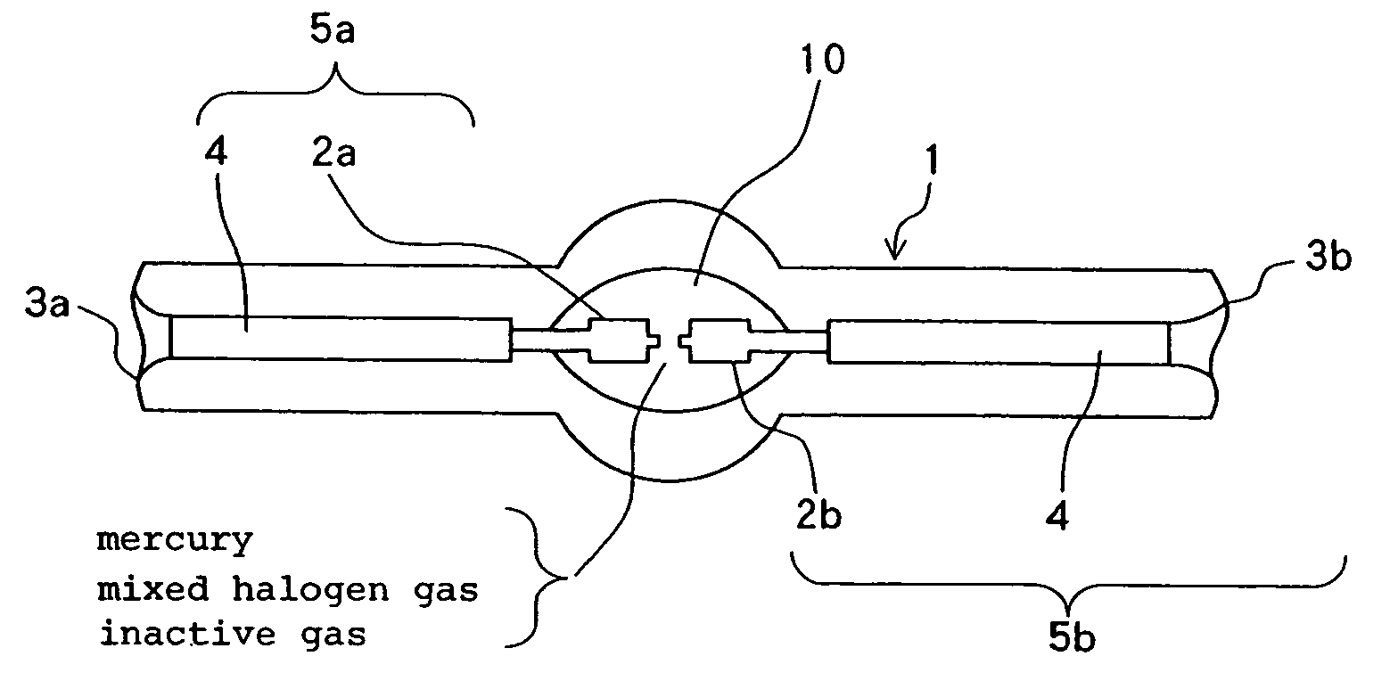
[0021]FIG. 1 shows in schematic cross section a high-pressure discharge lamp according to an embodiment of the present invention. As shown in FIG. 1, the high-pressure discharge lamp has lamp bulb 1 of silica glass with substantially spherical discharge space 10 defined centrally in its longitudinal direction, and a pair of electrodes 2a, 2b disposed in discharge space 10 in confronting relation to each other. The relationship between inner surface area S (mm2) of the bulb wall defining the discharge space 10 and electric power P (W) applied to the high-pressure discharge lamp is established such that bulb wall load L (W / mm2) is in the range of 0.8≦L<1.0.

[0022] Electrodes 2a, 2b are made of tungsten and are inserted from respective insertion holes 3a, 3b defined in the opposite ends of lamp bulb 1. Insertion holes 3a, 3b are hermetically sealed by rear portion of respective electrodes 2a, 2b which are covered with respective sheets of molybdenum foil 4 serving as a thermal buffer. ...

2nd embodiment

[0048] A high-pressure discharge lamp according to a second embodiment of the present invention will be described below. The high-pressure discharge lamp according to the second embodiment has a basic structure identical to that of the high-pressure discharge lamp shown in FIG. 1. Only those portions of the high-pressure discharge lamp according to the second embodiment which are different from the high-pressure discharge lamp shown in FIG. 1 will be described below.

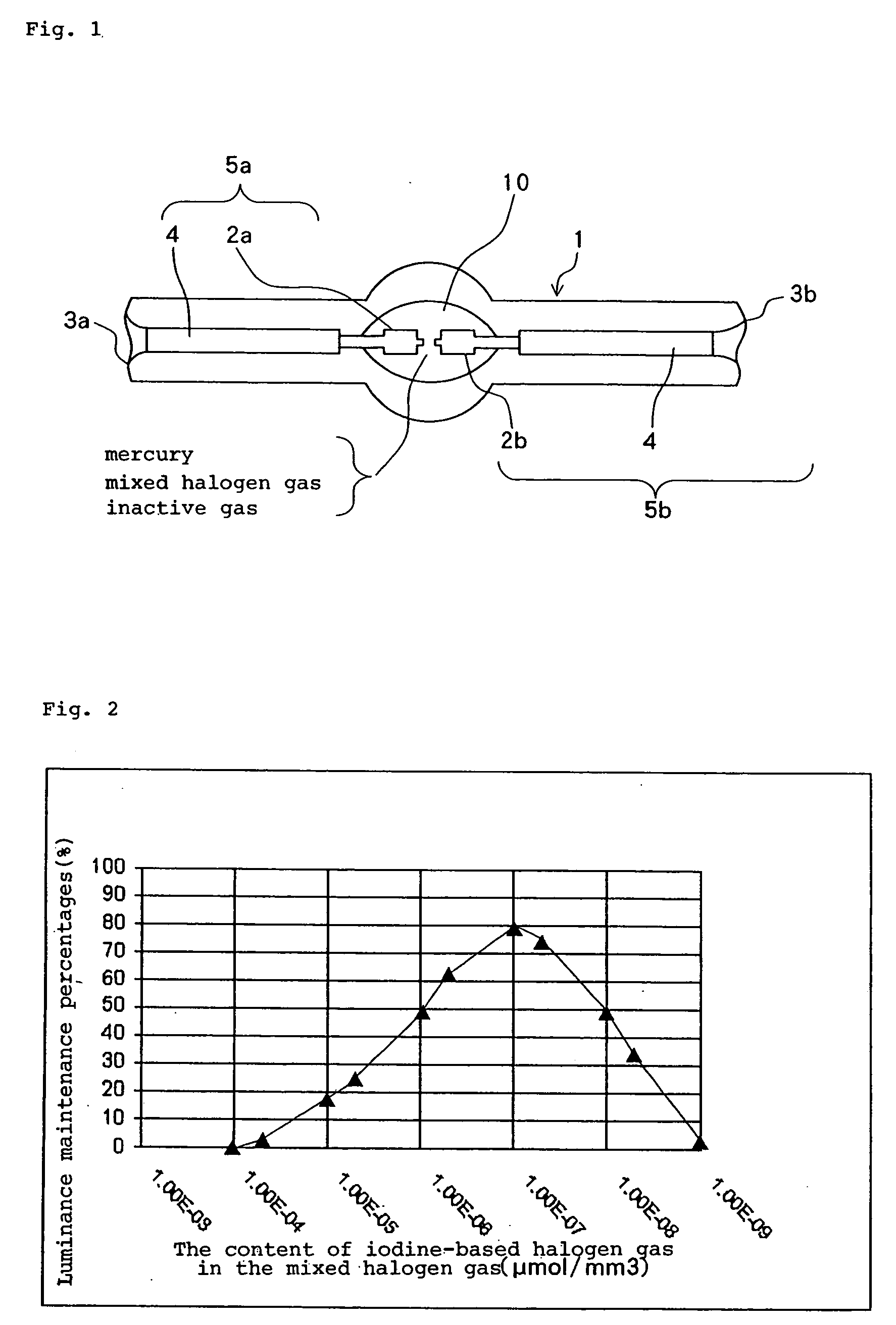
[0049] According to the second embodiment, the relationship between inner surface area S (mm2) of the bulb wall defining the discharge space and electric power P (W) applied to the high-pressure discharge lamp is established such that bulb wall load L (W / mm2) is in the range of 1.0≦L−7 μmol / mm3 to 10−5 μmol / mm3 and an iodine-based halogen gas and / or a chlorine-based halogen gas whose content in the mixed halogen gas is one digit smaller than the bromine-based halogen gas.

[0050] The high-pressure discharge lamp accordin...

3rd embodiment

[0052] A high-pressure discharge lamp according to a third embodiment of the present invention will be described below. The high-pressure discharge lamp according to the third embodiment has a basic structure identical to that of the high-pressure discharge lamp shown in FIG. 1. Only those portions of the high-pressure discharge lamp according to the third embodiment which are different from the high-pressure discharge lamp shown in FIG. 1 will be described below.

[0053] According to the third embodiment, the relationship between inner surface area S (mm2) of the bulb wall defining the discharge space and electric power P (W) applied to the high-pressure discharge lamp is established such that bulb wall load L (W / mm2) is in the range of 1.2≦L−6 μmol / mm3 to 10−4 μmol / mm3 and an iodine-based halogen gas and / or a bromine-based halogen gas whose content in the mixed halogen gas is one digit smaller than the chlorine-halogen gas.

[0054] The high-pressure discharge lamp according to the t...


PUM


Abstract

A high-pressure discharge lamp has a lamp bulb of silica glass encapsulating mercury, an inactive gas, and a mixed halogen gas containing at least two halogen gases, and at least a pair of electrodes disposed in the lamp bulb in confronting relation to each other. The type and content of a primary halogen gas whose content is the greatest in the mixed halogen gas are determined based on a bulb wall load.

Description

BACKGROUND OF THE INVENTION [0001] 1. Field of the Invention [0002] The present invention relates to a high-pressure discharge lamp for emitting light due to a plasma discharge in the presence of a mercury gas atmosphere, and a method of manufacturing such a high-pressure discharge lamp. [0003] 2. Description of the Related Art [0004] General high-pressure discharge lamps have a lamp bulb of silica glass with a substantially spherical discharge space defined centrally in its longitudinal direction, and a pair of electrodes of tungsten disposed in the discharge space in confronting relation to each other. The discharge space is filled with mercury, a halogen gas, and an inactive gas. The two electrodes are inserted from respective insertion holes defined in the opposite ends of the lamp bulb. The insertion holes are hermetically sealed by rear portion of the respective electrodes which are covered with respective sheets of molybdenum foil serving as a thermal buffer. [0005] When a tr...

Claims


Application Information

Patent Timeline
Patent Type & Authority Applications(United States)
IPC IPC(8): H01J9/38H01J9/395H01J17/20H01J61/12H01J61/20H01J61/26H01J61/82
CPCH01J9/38H01J9/395H01J61/822H01J61/20H01J61/26H01J61/12
Inventor NISHIDA, KAZUHISA
Owner USHIO DENKI KK
Learn More