Downhole clock synchronization apparatus and methods for use in a borehole drilling environment

a technology of synchronizing apparatus and synchronizing method, which is applied in the direction of instruments, borehole/well accessories, surveys, etc., can solve the problems of adversely affecting the accuracy of downhole clock, degrading downhole and reference clock, and no clock available which provides the required accuracy. , to achieve the effect of low accuracy requirements

Active Publication Date: 2005-01-13
WEATHERFORD TECH HLDG LLC
View PDF10 Cites 24 Cited by
  • Summary
  • Abstract
  • Description
  • Claims
  • Application Information

AI Technical Summary

Benefits of technology

[0009] Each deployed shuttle can be retained and stored within the borehole assembly for subsequent retrieval when the borehole assembly is eventually removed from the well borehole. As an alternate, shuttles can be allowed to pass through the borehole assembly and return to the surface via the circulating drilling fluid. As yet another alternate, the shuttle can be considered “disposable” and therefore deformed and destroyed after data transfer to the borehole assembly. Resulting debris from a destroyed shuttle is returned to the surface via the circulating drilling fluid. Destruction is economically feasible. Because of relatively low accuracy requirements, relatively inexpensive clocks can be used in the shuttles.

Problems solved by technology

No clocks are known to be available which provide the required accuracy in a borehole drilling environment, which typically involves elevated and varying temperature, significant shock and high vibration.
All of these factors adversely affect the accuracy of the downhole clock.
After a period of a day or more, synchronization between the downhole and reference clock degrades to a point that seriously jeopardizes the accuracy of any SWD measurements.
The establishment of any type of direct link is, however, typically economically and operationally costly in that it impedes the drilling process, can jeopardize the integrity of the well bore, is formation dependant, and lacks precision to obtain the required synchronization accuracy.

Method used


Image

  • Downhole clock synchronization apparatus and methods for use in a borehole drilling environment
  • Downhole clock synchronization apparatus and methods for use in a borehole drilling environment
  • Downhole clock synchronization apparatus and methods for use in a borehole drilling environment

Examples


Embodiment Construction

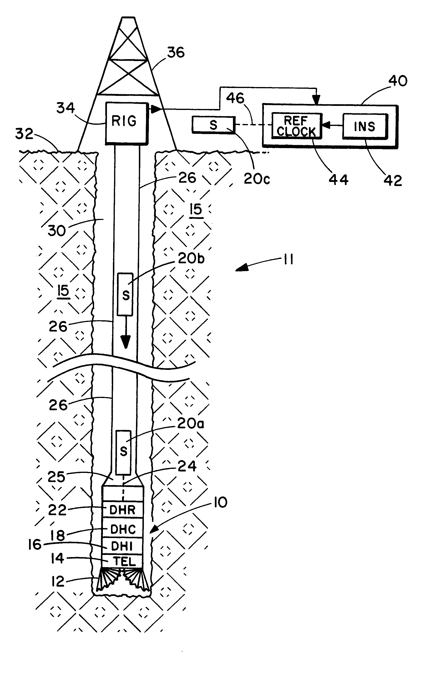
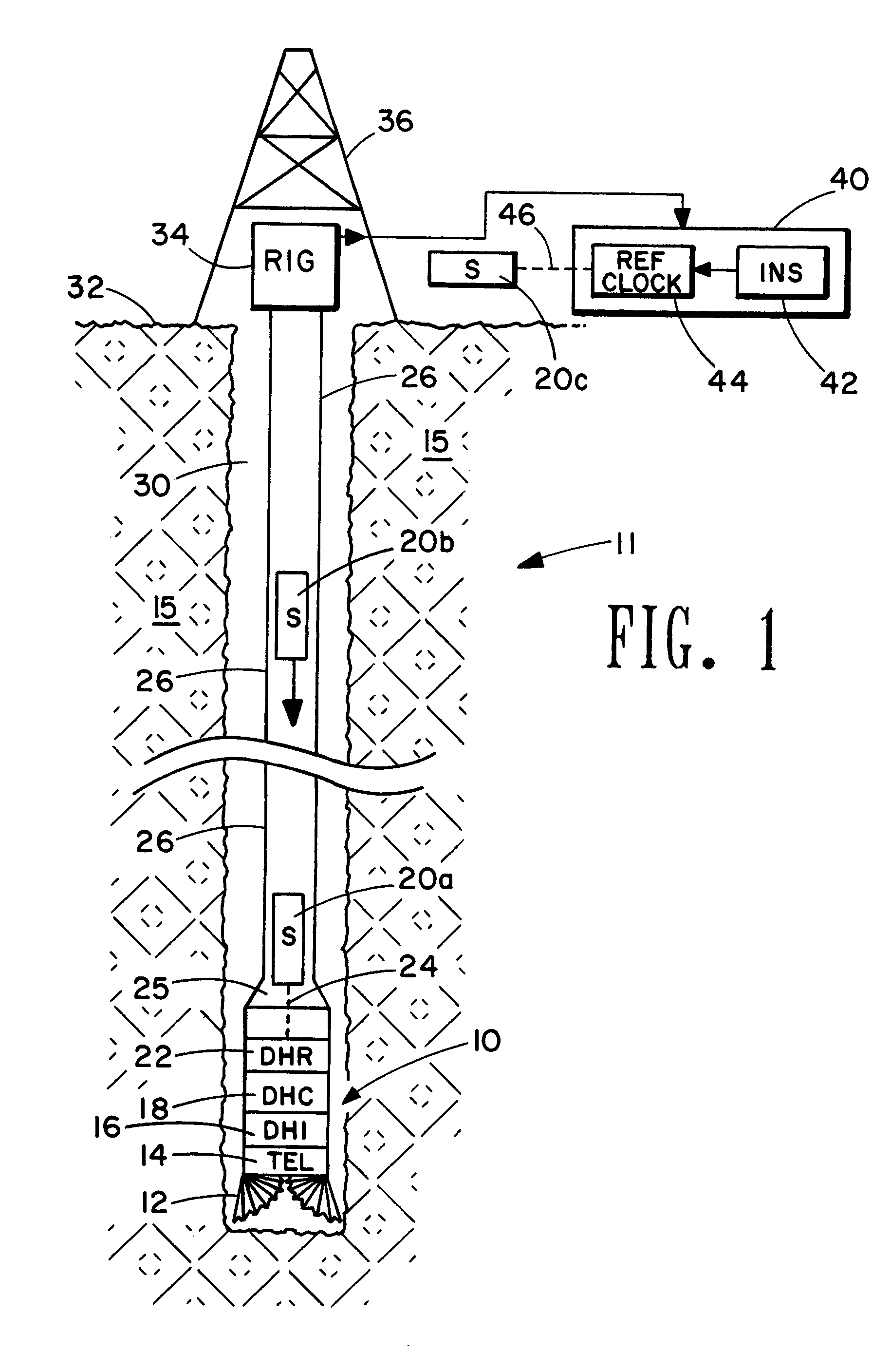
[0017] As discussed previously, reference clock and downhole clock synchronization (preferably to UTC) is maintained using a small shuttle clock conveyed between the surface of the earth and a downhole assembly. FIG. 1 conceptually illustrates a generic measurement system 11 for making borehole measurements and formation measurements while the borehole is being drilled. For purposes of discussion, it will be assumed that the system 11 is a seismic-while-drilling (SWD) system, which requires accurate synchronization between a reference clock and a downhole clock over an extended time period such as days.

[0018] Again referring to FIG. 1, a well borehole 30 is shown penetrating earth formation 15. The borehole 30 is advanced by means of a borehole assembly 10 comprising a drill bit 12. The borehole assembly 10 is operationally attached to a drill string 26 which is rotated by a rotary drilling rig 34 partially supported by a derrick 36. The borehole assembly 10 also comprises a teleme...


PUM


Abstract

Geophysical measurement system employed during the drilling of a well borehole. The system employs a reference clock disposed within equipment at the surface of the earth and a borehole assembly which houses a downhole clock and at least one sensor. The borehole assembly is operationally connected to a drill string, which advances the borehole. At least one synchronization shuttle apparatus containing a shuttle clock is conveyed downhole to the borehole assembly to synchronize the borehole clock with the reference clock. Reference and borehole clock synchronization is maintained at one millisecond or less over a period of days. Outputs from the reference clock and borehole clock and sensor are combined to obtain a measure of a geophysical parameter of interest. Although the measurement system is particularly applicable to seismic-while-drilling measurements, it can be used in a wide variety of clock driven geophysical measurements.

Description

BACKGROUND OF THE INVENTION [0001] This invention is directed toward geophysical measurement apparatus and methods employed during the drilling of a well borehole. More specifically, the invention is directed toward seismic measurement apparatus and methods for synchronizing a clock within the borehole with a reference clock at the surface of the earth using a shuttle system. A synchronization shuttle apparatus is inserted and conveyed within the borehole to operationally connect with apparatus containing the borehole clock and thereby synchronize the borehole clock with the reference clock. [0002] Systems for measuring parameters within a well borehole, and geophysical parameters of earth formation in the vicinity of the well borehole, typically fall within two categorizes. The first category includes systems that measure parameters after the borehole has been drilled. These systems include wireline logging, tubing conveyed logging, slick line logging, production logging, permanent...

Claims


Application Information

Patent Timeline
Patent Type & Authority Applications(United States)
IPC IPC(8): G01V1/40
CPCG01V1/40
Inventor MINTO, JAMESSORRELLS, MARTINHARVEY, PETER
Owner WEATHERFORD TECH HLDG LLC
Why Eureka
Try Eureka