Backlighting construction for use in computer-based display systems having direct and projection viewing modes of operation

a technology of backlighting and computer-based display system, which is applied in the field of computer-based systems, can solve the problems that certain percentage of scattered light rays no longer meet the conditions, and achieve the effect of minimal light scattering

Inactive Publication Date: 2005-01-13
FARIS SADEG M +1
View PDF11 Cites 21 Cited by
  • Summary
  • Abstract
  • Description
  • Claims
  • Application Information

AI Technical Summary

Benefits of technology

[0036] During the projection viewing mode, rear housing panel and light guiding panel are hingedly reconfigured and supported at about a 45 degree angle with respect to the rear light transmission aperture, and light is preferably not produced from the light producing means. Instead, during the projection viewing mode, light is produced from an external light source disposed beneath the supported rear housing panel and projected through the light guiding panel. During the projection viewing mode, the light extraction pattern is disposed behind the light reflective surface and thus projected light rays from the external light source are reflected off the light reflective surface, and not the light diffusive structures mounted on the light guiding panel, permitting the reflected light to pass freely through thin lens and LCD panel subassembly with minimal light scattering. During the projection viewing mode, the projected light rays emerge from the LCD panel modulated in spatial intensity and after passing through an external projection lens, form images on a viewing surface, such as a wall surface or projection screen. This novel approach eliminates altogether the need for additional bulky overhead projection devices required by all prior art systems.

Problems solved by technology

In the direct viewing mode, the light extracting pattern scatters light rays internally reflected within the light guiding panel, and as such, a certain percentage of these scattered light rays are no longer satisfy the conditions for total internal reflection within the light guiding panel.

Method used


Image

  • Backlighting construction for use in computer-based display systems having direct and projection viewing modes of operation
  • Backlighting construction for use in computer-based display systems having direct and projection viewing modes of operation
  • Backlighting construction for use in computer-based display systems having direct and projection viewing modes of operation

Examples


Embodiment Construction

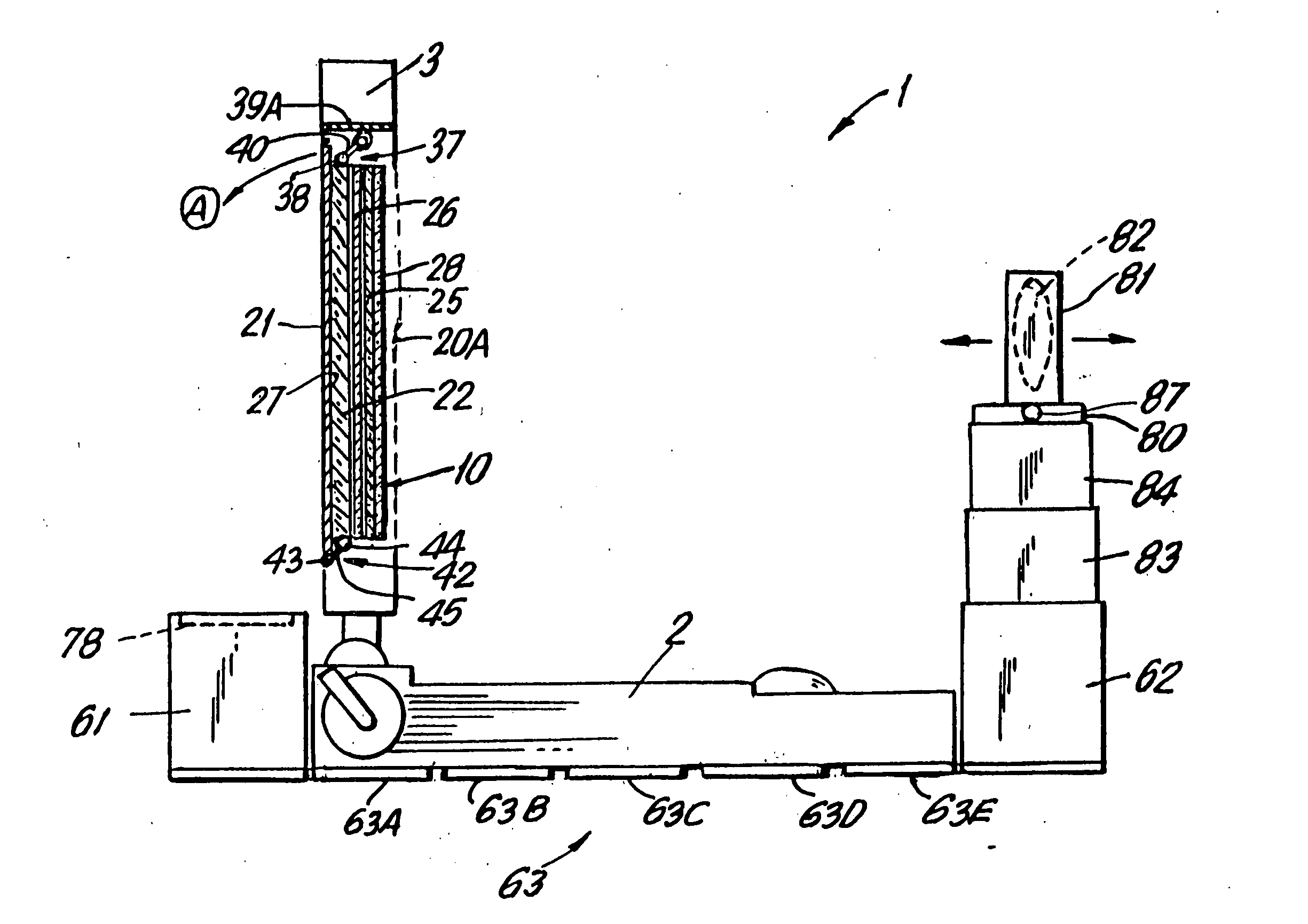
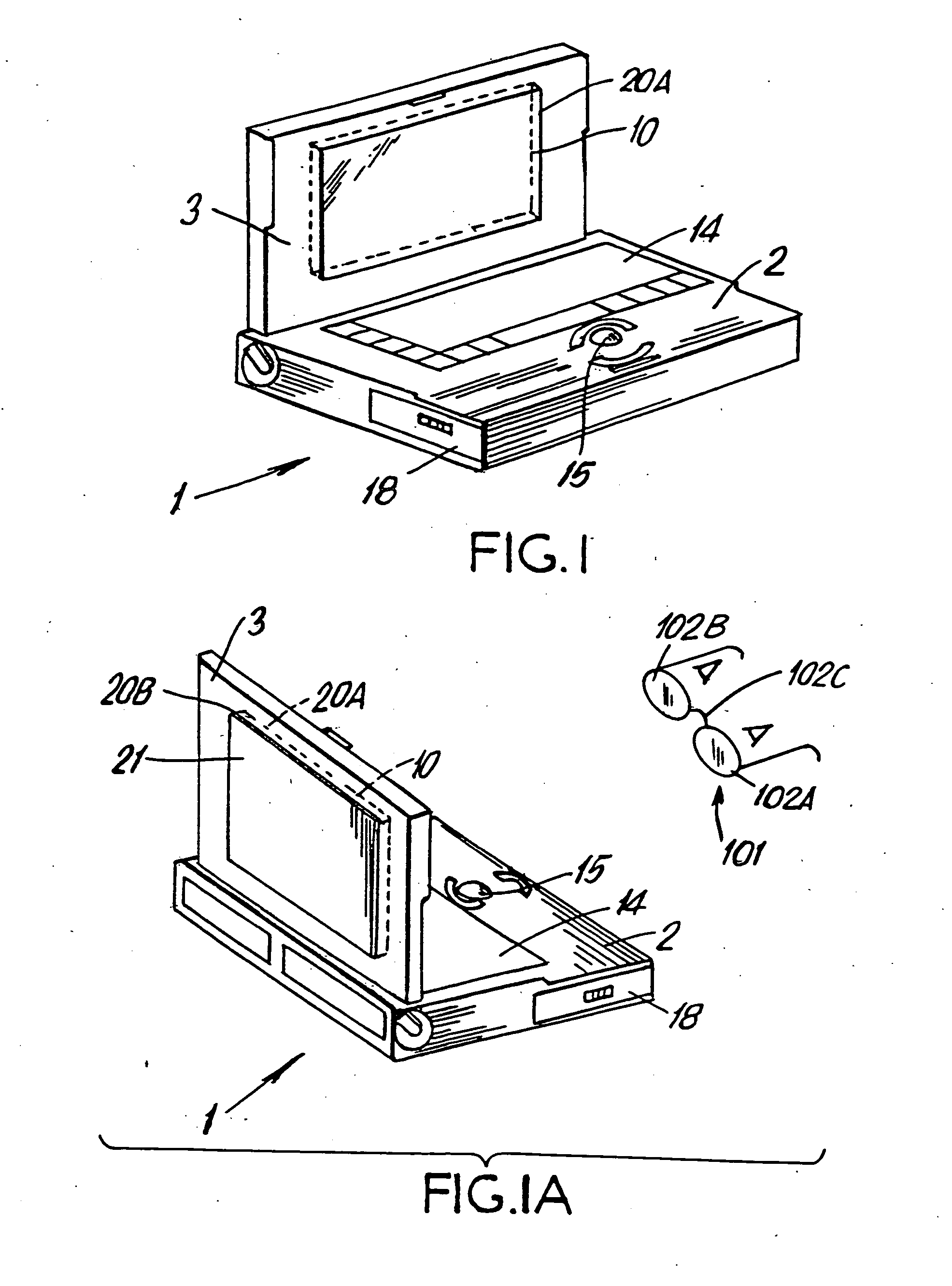
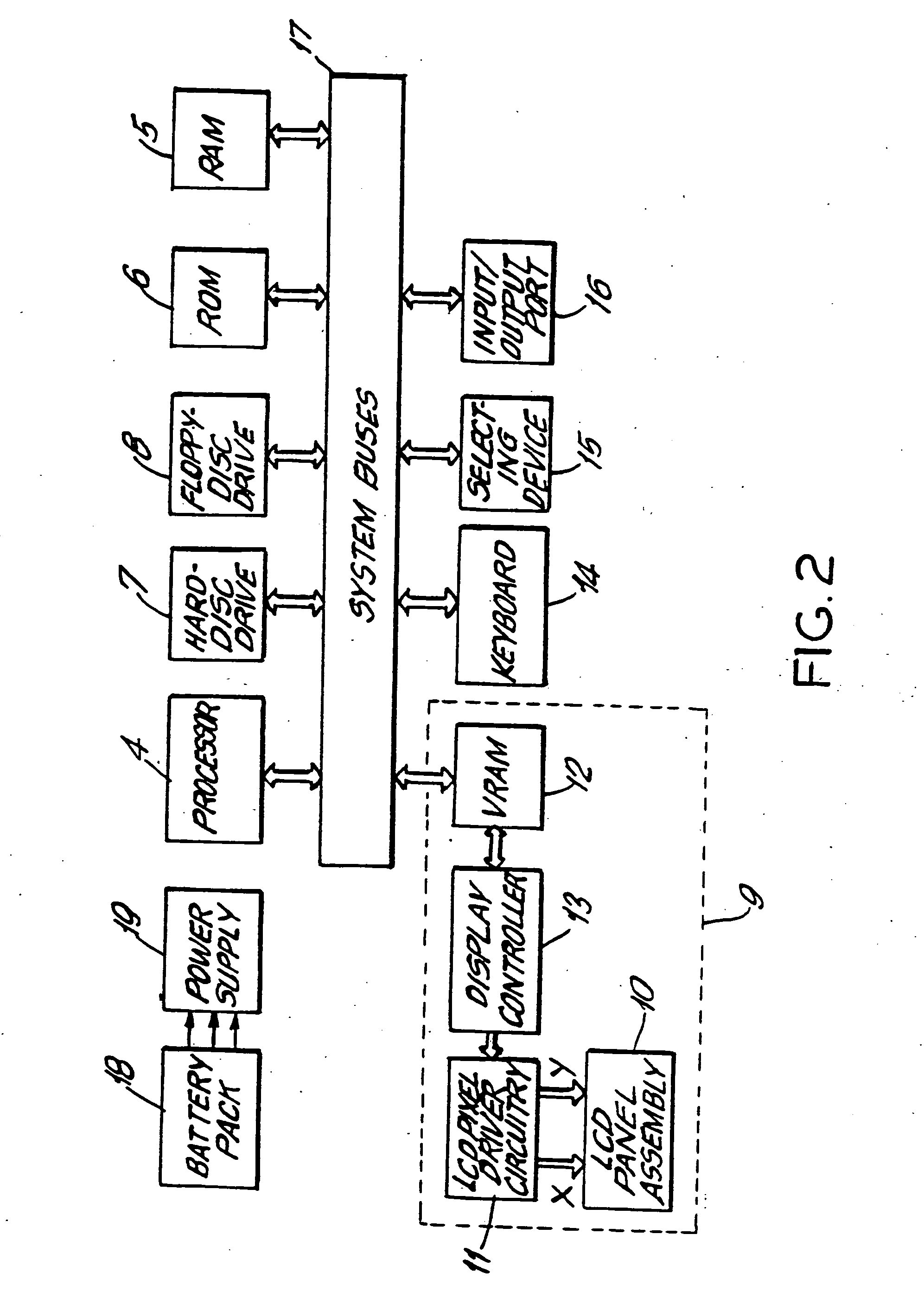
[0066] In general, the backlighting construction of the present invention can be used in various backlighting applications. In the illustrative embodiments, the backlighting construction is incorporated into six different portable computer-based systems, namely: the portable notebook / laptop computer system illustrated in FIGS. 1 to 4C and 5 to 5A; the portable notebook / laptop computer system illustrated in FIG. 4C in particular, the portable image display device illustrated in FIGS. 9 to 9B; the portable pen-computing device illustrated in FIGS. 10 to 10B; the portable notebook / laptop computer system illustrated in FIG. 11; the portable notebook / laptop computer system illustrated in FIG. 12; and the portable notebook / laptop computer system illustrated in FIG. 13. It is understood, however, that the backlighting construction of the present invention may be used with other types of computer-based systems and equipment, including computer monitors, optical transparencies, film structur...


PUM

PropertyMeasurementUnit
thicknessaaaaaaaaaa
angleaaaaaaaaaa
thicknessaaaaaaaaaa

Abstract

A reconfigurable backlighting construction for use in portable computer-based systems having direct and projection viewing modes of operation. In the illustrative embodiments of the present invention, the backlighting construction is integrated with a LCD display panel, a micropolarization panel, and a touch-screen writing panel to provide several different types of portable computer-based systems including, for example, a portable notebook computer, a computer-driven image display device, and a portable pen-computing device. In general, each of these computer-based systems are capable of selectively displaying color video images on an actively driven display surface, or projecting such video images onto a wall surface or projection screen without the need for a bulky overhead projector, required by all prior art systems. These computer-based systems can be easily reconfigured for projection viewing without physical removal of the light guiding panel and its light diffusing structures. If desired, these computer-based systems can be used to directly view “spatially-multiplexed” images of 3-D objects or imagery during the direct viewing mode, and when desired these spatially-multiplexed images can be projected onto a wall surface or projection screen during the projection viewing mode. When the spatially-multiplexed images are viewed through electrically-passive polarized glasses, the 3-D object is perceived with stereoscopic depth sensation in either mode of viewing. A portable light projection accessory device is provided for use with the portable computer-based systems of the present invention. In the illustrative embodiments, the portable light projection device has first and second housing portions that are interconnected by a foldable structure that permits the first and second housing portions to be selectively reconfigured for simple trouble-free use during the projection viewing mode of operation, and for compact storage during the direct viewing mode of operation.

Description

RELATED CASES [0001] This is a Continuation-in-Part of copending application Ser. No. 08 / 230,779 entitled “ELECTRO-OPTICAL BACKLIGHTING PANEL FOR USE IN COMPUTER-BASED DISPLAY SYSTEMS AND PORTABLE LIGHT PROJECTION DEVICE FOR USE THEREWITH” by Sadeg M. Faris, filed Apr. 21, 1994, which is incorporated herein by reference as if set forth fully herein.BACKGROUND OF INVENTION [0002] 1. Field of Invention [0003] The present invention relates to computer-based systems having both direct and projection viewing modes of operation. [0004] 2. Brief Description of the Prior Art [0005] Presently, most portable computing systems include a flat liquid crystal display(LCD) panel for directly viewing video imagery displayed thereon. Portable computer systems of this type include notebook, laptop, and palmtop computers. [0006] In general, prior art. LCD display panels have essentially the same basic construction in that each includes a conventional backlighting structure affixed to the rear surface ...

Claims


Application Information

Patent Timeline
Patent Type & Authority Applications(United States)
IPC IPC(8): G02B30/25G02F1/1334G02F1/1335G02F1/13357G03B21/132G03B21/30G06F1/16G06F3/033G06F3/041G06F3/048H04N5/74H04N13/239
CPCB82Y15/00H04N13/0497G02F1/1334G02F1/1336G02F2001/133538G02F2001/133627G03B21/132G03B21/30G06F1/1616G06F1/1626G06F1/1632G06F1/1639G06F1/1645G06F3/041G06F3/0412G06F3/0414G06F3/0488H04N5/7441H04N5/7491H04N9/3141H04N13/0239H04N13/0246H04N13/0296H04N13/0422H04N13/0434H04N13/0438H04N13/0454H04N13/0459G02B27/26H04N13/337H04N13/341H04N13/324H04N13/246H04N13/296H04N13/363H04N13/359H04N13/239H04N13/398G02B30/25G02F1/133538G02F1/133627
Inventor FARIS, SADEG M.TUNG, CARL
Owner FARIS SADEG M
Why Eureka
Try Eureka