Reception method and reception device estimating reception quality and communication system using the reception device

Inactive Publication Date: 2005-01-13
INTERDIGITAL PATENT HLDG INC
View PDF11 Cites 16 Cited by
  • Summary
  • Abstract
  • Description
  • Claims
  • Application Information

AI Technical Summary

Benefits of technology

[0015] With the above configuration, it is possible to arrange the transmitting data with the higher importance information at the position with the higher communication reliability and communicate it in accordance with the variation in received signal quality depending on the in-frame position due to various factors in a down-link communication system. Consequently, the communication services are improved.
[0016] According to the present invention, it is possible to estimate the variation in received signal quality depending on the position in the frame which is caused by various property deteriorating factors in the processing from transmitting the transmitting data from the transmitting station to receiving the data by the receiving station via the transmission path, and to efficiently use the estimating result in the data processing unit at the latter stage. With the foregoing configuration and advantages, the levels of received signal qualities at the specific position in the frame can be detected and the data processing unit at the latter state can improve the precision of the processing based on the quality information. For example, the data with the low quality can be deleted. Further, it is possible to arrange the transmitting data with the higher importance information at the position wit

Problems solved by technology

However, the symbol apart from the pilot symbol is not fully interpolated and the quality might deteriorate depending on the precision of interpolation processing.
As mentioned above, since the communication quality might vary in the processing units, the communication qualities at the positions in a finally-obtained received data frame are not uniform and are varied.
Specifically, the occurrence of communication error at the sequence header portion or the picture header potion influences the entire sequence block and picture header portion, thus excessively deteriorating the image quality.
However, the occurrence of the communication error in a DCT encoding data unit doe not exert the in

Method used


Image

  • Reception method and reception device estimating reception quality and communication system using the reception device
  • Reception method and reception device estimating reception quality and communication system using the reception device
  • Reception method and reception device estimating reception quality and communication system using the reception device

Examples


first embodiment

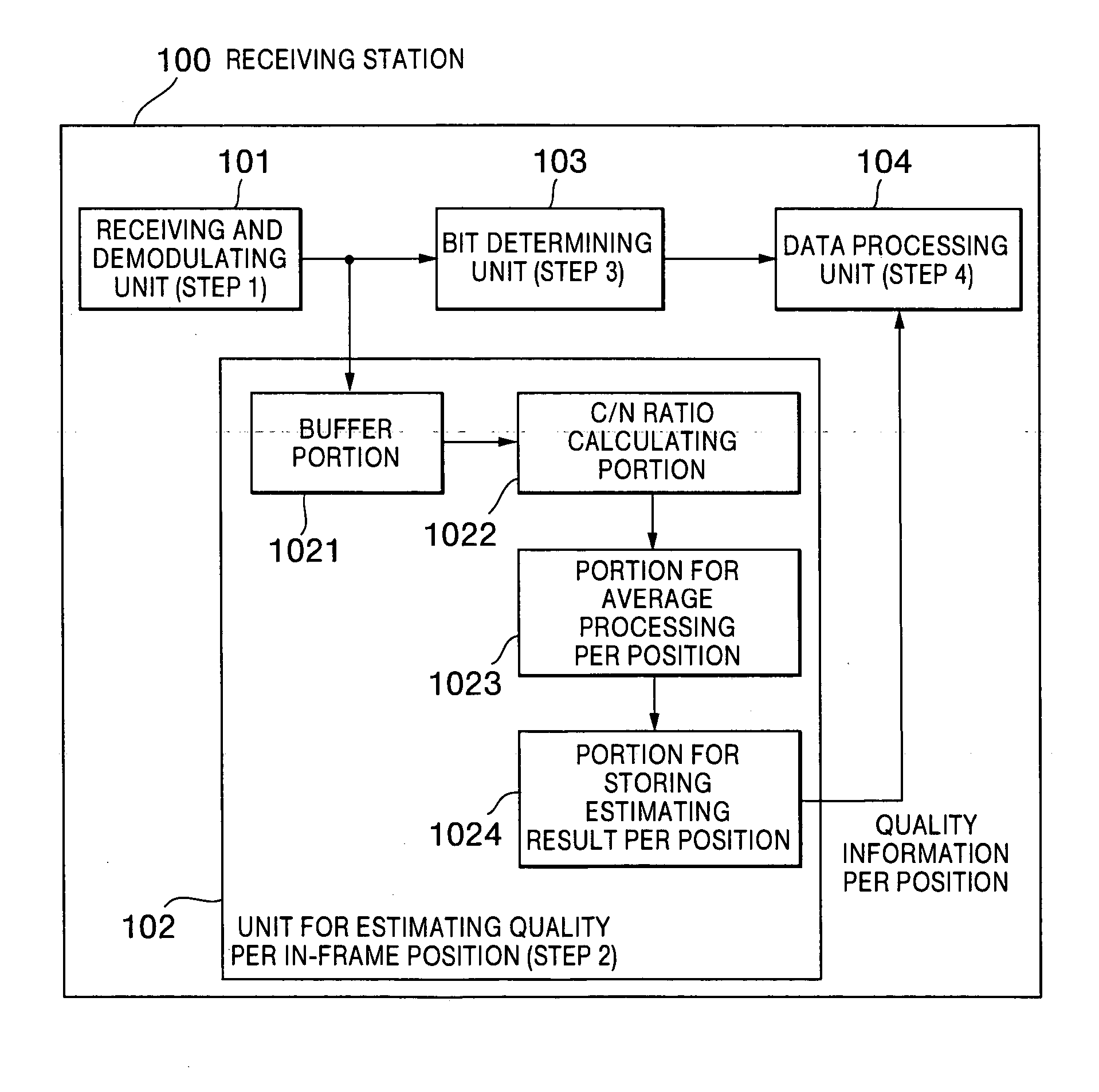
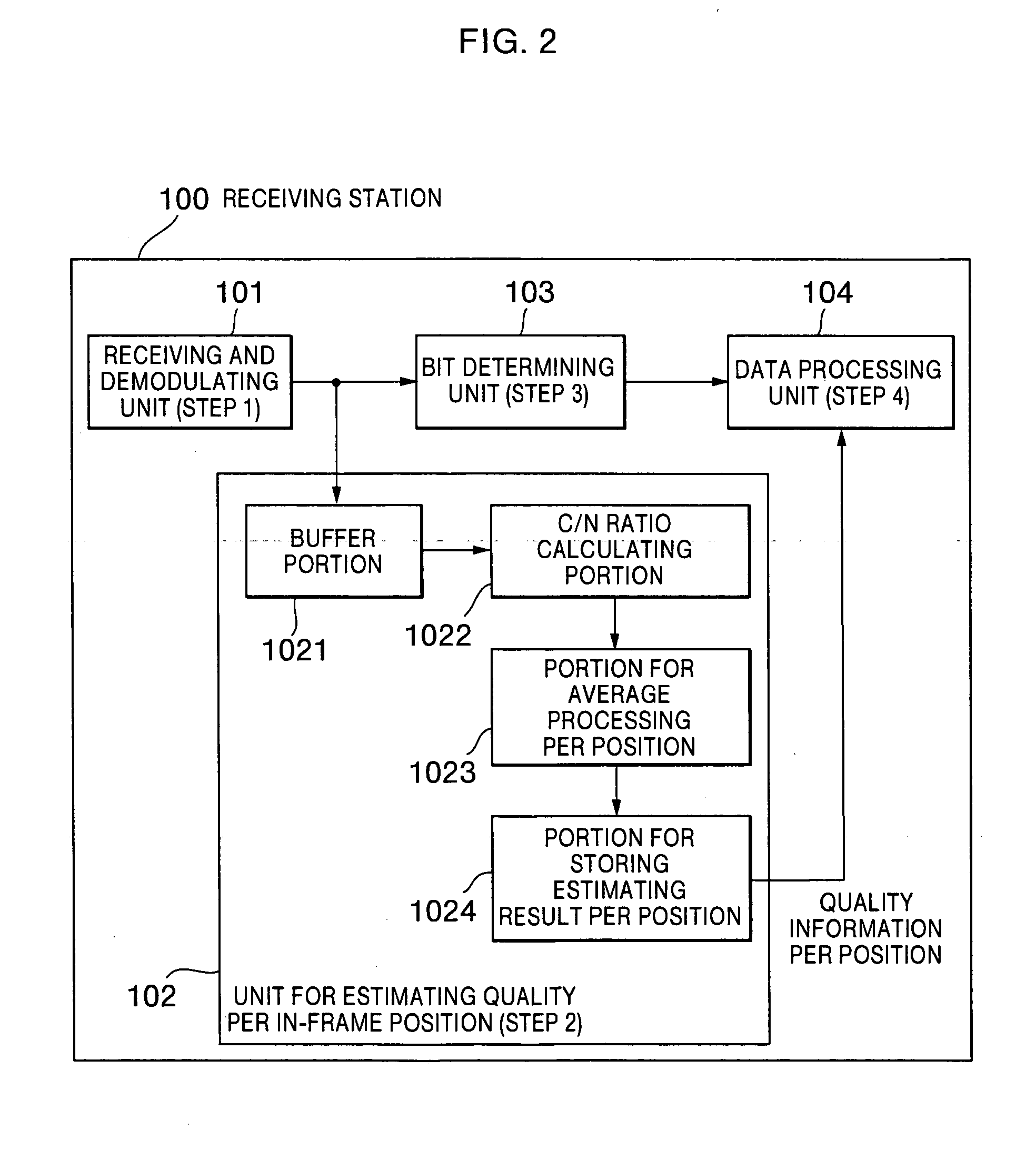
[0030] A first embodiment of the present invention will be described. FIG. 2 shows the configuration and the operation of a receiving station 100 according to the first embodiment. According to the first embodiment, the received signal quality is estimated per position in a received-data frame based on a receiving and estimating result of the receiving station 100, and an estimating result is obtained. Although a received signal is subjected to predetermined modulation processing, the modulating method is not limited. For example, the orthogonal frequency division multiplexing (hereinafter, referred to as the OFDM) is used. At each subcarrier in OFDM, 64-level QAM with gray coding is used. Communication data is transmitted based on a frame structure containing a predetermined number of pieces of data or a predetermined formats.

[0031] In the receiving station 100, a receiving and demodulating unit 101 receives and demodulates a modulated signal received based on the frame unit and o...

second embodiment

[0047] Next, the second embodiment of the present invention will be described. FIG. 3 shows the configuration of a communication system according to the second embodiment. According to the second embodiment, the interactive communication is possible between a tranceiver station 200 as a first communication station and a tranceiver station 210 as a second communication station. In the communication from the transceiver station 200 to the transceiver station 210, a method for arranging the data in a communication frame is dynamically changed. A communication signal is subjected to predetermined modulation processing and, however, the modulating method is not limited according to the second embodiment. Here, the first modulation uses the 64-level QAM in which the signal points are arranged by the gray code and then the communication signal is subjected to the OFDM processing. According to the second embodiment, a communication link from the transceiver station 200 to the transceiver st...

third embodiment

[0075] Next, a description is given of the third embodiment of the present invention with reference to FIG. 7. FIG. 7 shows a communication system according to the third embodiment of the present invention. According to the third embodiment, the interactive communication is executed between a transceiver station 300 as a first communication station and a transceiver station 310 as a second communication station. In the communication from the transceiver station 300 to the transceiver station 310, an MIMO (Multi-Input Multi-Output) communication channel is used. The configuration of the transceiver station300 is basically the same as that of the transceiver station 200 as shown in FIG. 3. Unlike the transceiver station 200, the transceiver station 300 includes an MIMO transmitting unit 301, in place of the transmitting and modulating unit 203. Further, the configuration of the transceiver station 310 is basically the same as that of the transceiver station 210 as shown in FIG. 3. Unl...


PUM


Abstract

Variation in received signal qualities at positions in a frame is estimated so as to improve a communication quality. In communication from a transmitting station to a receiving station, a received signal quality is estimated per data position in a data frame received by the receiving station, thus to grasp situations of the received signal quality varied depending on a position which is caused by various factors of property deterioration in a process from transmitting communication data from the transmitting station to receiving it by the receiving station via a transmission path. Further, an estimating result is supplied to a data processing unit and used at a latter stage. The estimating result is notified to the transmitting station and arrangement of transmitting data is reconstructed on the transmitting station side. The arrangement of the transmitting data is properly changed in accordance with importance of the communication data. Further, the rearranged transmitting data is properly restored on the receiving station side, thereby obtaining received data and improving a quality of a communication service.

Description

BACKGROUND OF THE INVENTION [0001] 1. Field of the Invention [0002] The present invention relates to a receiving method and a receiving apparatus for estimating the received signal quality, and a communication system using the receiving apparatus. [0003] 2. Description of the Prior Art [0004] Various technologies are introduced to conventional communication systems, in particular, a radio communication system, for the purpose of the high efficiency of a transfer method and the increase in transfer capacity. For example, the abovementioned technologies include a multivalue modulating technology, e.g., a quadrature amplitude modulating (QAM) method serving as a modulating method, an orthogonal frequency division multiplexing (OFDM) method serving as a multiplexing method, punctured convolution coding which is obtained by combining convolution coding and punctured processing serving as codec processing, and turbo coding, and the like. Further, one of the abovementioned conventional tec...

Claims


Application Information

Patent Timeline
IPC IPC(8): H04L27/36H04J11/00H04L1/00H04L1/06H04L1/20
CPCH04L1/0001H04L1/20H04L1/06H04L1/0026
Inventor ABE, KATSUAKIORIHASI, MASAYUKIMURAKAMI, YUTAKAMATSUOKA, AKIHIKOSAKAMOTO, TAKENORI
Owner INTERDIGITAL PATENT HLDG INC
Why Eureka
Try Eureka