Laser transponder

a transponder and laser technology, applied in the field of laser transponders, can solve the problems of reducing the performance of the two others, overheating the laser diode, rendering the system useless for that period, etc., and achieves the effect of low energy, not overheating, and high reliability of the communication link

Inactive Publication Date: 2003-11-06
BLINDER INT
View PDF0 Cites 8 Cited by
  • Summary
  • Abstract
  • Description
  • Claims
  • Application Information

AI Technical Summary

Benefits of technology

0017] Therefore it is also seen in many other applications that IR-diodes have been used. These have the advantage that they work at very low energies and thereby do not overheat. However, such IR-diodes emit a maximum energy at 850 nm and at the operating wavelength of common laser emitting and laser receiving devices, which is at 905 nm, they only emit 20% of the energy emitted at 850 nm, which creates the need for several IR-diodes where you only need one laser diode.
0018] Yet another advantage of making it possible to have the laser diode to work continuously is that it can work with much higher energies than an IR-diode. Typically, an IR-diode emits light with 100 mW where common laser diodes can emit up to 50W and thereby creating a much higher reliability of the communication link.
0019] Accordingly, the invention provides a laser transponder and method that can recognize a laser-based speed monitor and generate a signal that contains enough information to jam the specific speed monitor, thereby avoiding large energy signals and making it possible to use a laser diode continuously and in a way that prevents the laser transponder to be detected by the laser-based speed monitor and without overheating the laser diode.

Problems solved by technology

However, the transmission speed, the amounts of data transmitted and the reliability of the link are all closely connected and an improvement in one parameter will reduce the performance of the two others.
Further the growing demand for yet smaller electronic circuitry adds even another factor to take into account, since smaller systems creates larger thermal problems.
However when triggered by a signal from a speed monitor these systems will respond with a high energy signal, covering a wide band of possible frequencies, which will risk overheating the laser diode if not disabled for a period of time afterward, rendering the systems useless for that period.

Method used


Image

  • Laser transponder
  • Laser transponder
  • Laser transponder

Examples


Embodiment Construction

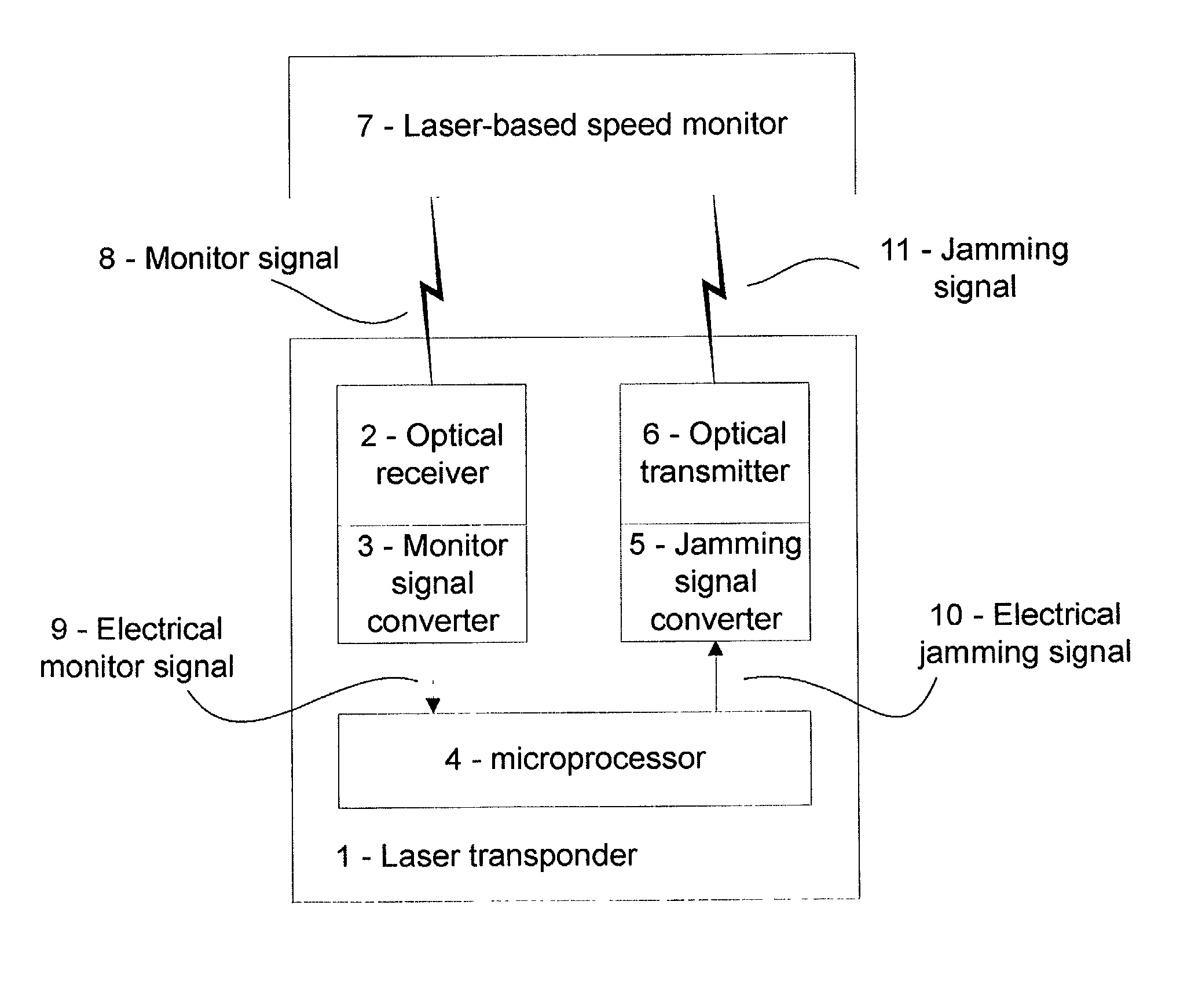
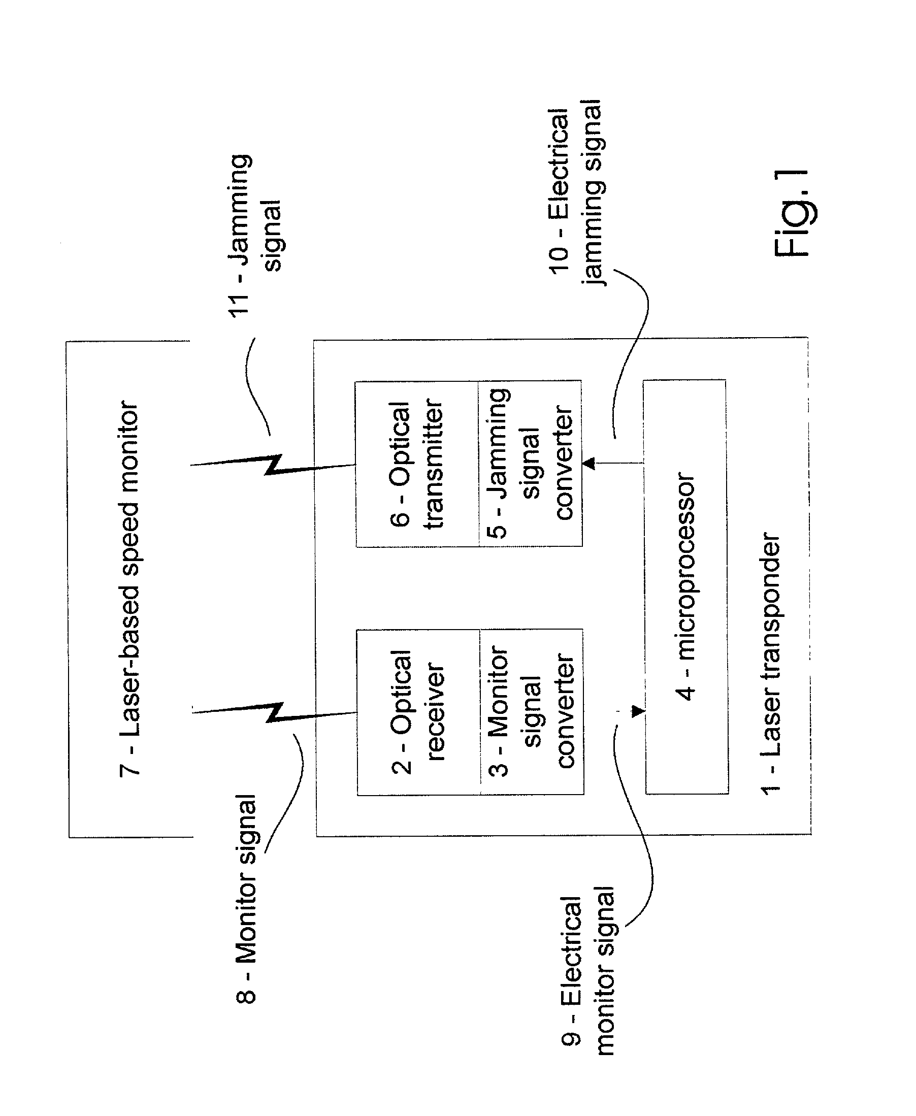
[0026] As shown in FIG. 1, a laser transponder 1 in accordance with the invention comprises an optical receiver 2, a monitor signal converter 3, a microprocessor 4, a jamming signal converter 5 and an optical transmitter 6.

[0027] The optical transmitter 6 is in one embodiment a laser diode having typically a wavelength of 904-905 nm, and is in another embodiment an IR diode with a typical wavelength of 870 nm.

[0028] The microprocessor 4 stores in a database reference values for the frequency of at least some of a number of known monitor signals, and for each of these reference values also stores a corresponding value for another frequency of the jamming signal. In one embodiment these reference values are changeable.

[0029] During operation, a laser-based speed monitor 7 transmits a monitor laser signal 8, which is received by the optical receiver 2. The optical receiver transmits the monitor laser signal to the monitor signal converter 3, which in turn converts this signal into an e...


PUM


Abstract

A laser transponder for disabling a laser-based speed monitor which is transmitting a monitor laser beam at a moving vehicle by transmitting a jamming laser beam to the laser-based speed monitor. The monitor laser beam is in the shape of a monitor signal that includes monitor pulse trains emitted at a first frequency, while the jamming laser beam is in the shape of a jamming signal that includes jamming pulse trains emitted at a second frequency.

Description

TECHNICAL FIELD[0001] The present invention relates to a laser transponder for disabling a laser-based speed monitor, which is transmitting a monitor laser beam at a moving vehicle by transmitting a jamming laser beam to the laser-based speed monitor.BACKGROUND ART[0002] Laser transponders for optically receiving and emitting information are today widely used in the fields of communication, surveillance and other areas where exchange of information is of interest.[0003] There is however a growing demand for processing the information with a higher reliability of the communication link.[0004] However, the transmission speed, the amounts of data transmitted and the reliability of the link are all closely connected and an improvement in one parameter will reduce the performance of the two others. Further the growing demand for yet smaller electronic circuitry adds even another factor to take into account, since smaller systems creates larger thermal problems.[0005] U.S. Pat. Nos. 5,767...

Claims


Application Information

Patent Timeline
Patent Type & Authority Applications(United States)
IPC IPC(8): G01S7/483G01S7/495G01S17/58
CPCG01S7/483G01S7/495G01S17/58H04K3/42H04K2203/22H04K3/62H04K3/825H04K2203/14H04K3/45H04K3/86
Inventor BOGH-ANDERSEN, TORBEN
Owner BLINDER INT
Why Eureka
Try Eureka