Method and apparatus for determining the write delay time of a memory

Active Publication Date: 2005-01-13
VIA TECH INC
View PDF4 Cites 26 Cited by
  • Summary
  • Abstract
  • Description
  • Claims
  • Application Information

AI Technical Summary

Benefits of technology

[0012] It is therefore an object of the invention to provide a method and an apparatus for quickly determining the write delay time of a memory.

Problems solved by technology

However, the checking method, which is mentioned above and typically executed by the BIOS (Basic Input / Output System) of the computer, consumes much time.
Because the speed for the CPU to read the command from the ROM is not quick enough and the BIOS further has to perform the identification by reading the pattern from the memory, the overall checking procedure for the write delay time is very slow, and the time for booting the computer will be lengthened.

Method used


Image

  • Method and apparatus for determining the write delay time of a memory
  • Method and apparatus for determining the write delay time of a memory
  • Method and apparatus for determining the write delay time of a memory

Examples


Embodiment Construction

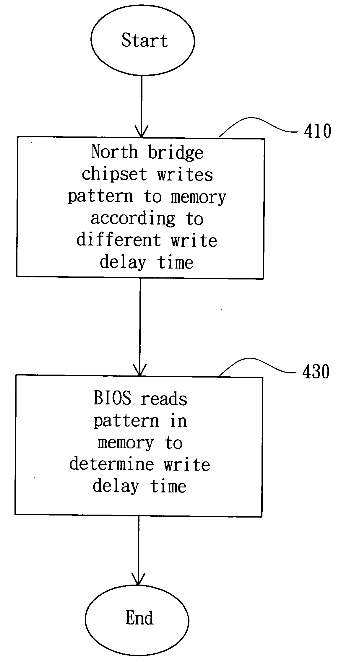
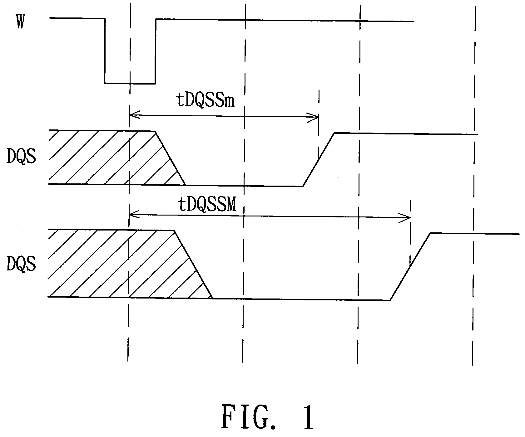
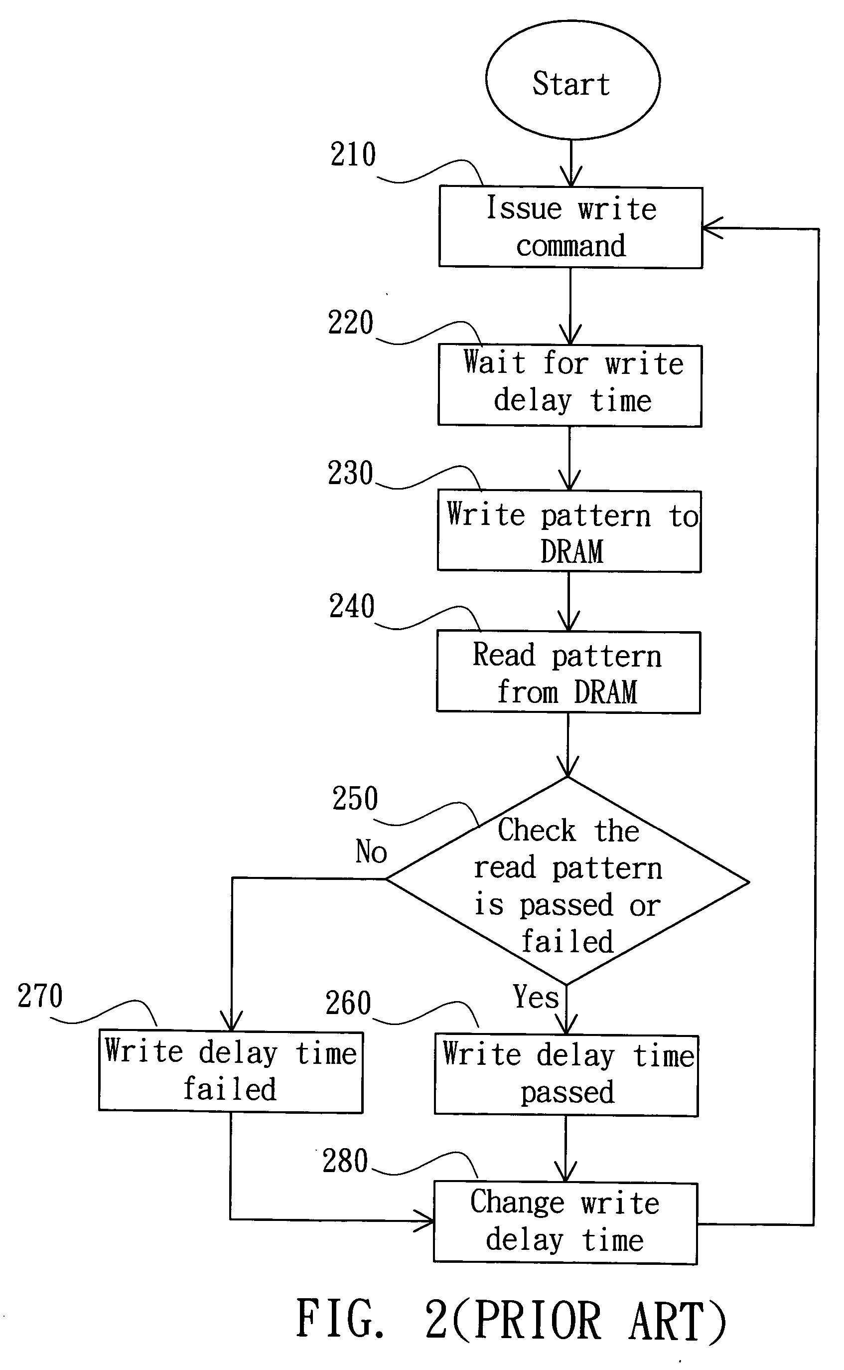
[0022] When the computer is just booted, various hardware have to be initialized by various operations, which are executed by the BIOS (Basic Input / Output System) in the computer. The initialization for the memory is to determine its write delay time. The computer may be simultaneously equipped with various memories manufactured by different manufacturers, and the properties of the memories are different. Therefore, the acceptable write delay time for each memory has to be found in order to ensure the correctness of data access. The conventional method for checking the write delay time of the memory is executed in the BIOS of the computer. The BIOS is located in a ROM (Read Only memory), which is electrically connected to the south bridge and has a very slow I / O speed with respect to the outside. Because the speed for the CPU to read the command from the ROM is not quick enough and the BIOS further has to perform the identification by reading the pattern from the memory, the overall...


PUM


Abstract

A method and apparatus for determining the write delay time of a memory are provided. The apparatus includes a CPU, a memory, a north bridge chipset, a south bridge and a BIOS. The north bridge chipset, which is connected to the CPU and the memory, writes a pattern to the memory according to different write delay times. The BIOS reads the pattern stored in the memory, and checks the correctness of the read pattern to determine the common write delay time.

Description

[0001] This application claims the benefit of Taiwan application Serial No. 92118535, filed Jul. 07, 2003. BACKGROUND OF THE INVENTION [0002] 1. Field of the Invention [0003] The invention relates to a method and apparatus for determining the write delay time of a memory, and more particularly to a method and apparatus for adjusting the write delay time in a DRAM (Dynamic Random Access Memory). [0004] 2. Description of the Related Art [0005] A typical electrical product, such as a computer, has DRAMs (Dynamic Random Access Memory) for temporarily storing data, programs, and the like for the processor. The computer may operate more smoothly as the capacity of the DRAM gets larger. Therefore, the current computer is configured such that several DRAMs may be inserted into the computer for the user to conveniently expand according to the requirement. The DRAM may be, for example, a DDR (Double Data Rate) dynamic random access memory. [0006] After a write command is issued to the memory,...

Claims


Application Information

Patent Timeline
IPC IPC(8): G06F1/04G06F13/42G11C7/10G11C7/22G11C11/4076G11C29/50G11C29/56
CPCG06F13/4239G11C7/1078G11C7/1093G11C7/22G11C11/401G11C2207/2254G11C29/50G11C29/50012G11C29/56G11C29/56012G11C11/4076
Inventor CHU, SIMON
Owner VIA TECH INC
Why Eureka
Try Eureka