Protective suit ventilated by self-powered bellows

a technology of bellows and protective suits, which is applied in the direction of inhalators, ventilation protection, heat protection, etc., can solve the problems of avoiding the protection of suits, avoiding the protection high production costs of previously disclosed suits, so as to achieve the maximum area of the body

Inactive Publication Date: 2005-01-20
KK TOSHIBA
View PDF9 Cites 20 Cited by
  • Summary
  • Abstract
  • Description
  • Claims
  • Application Information

AI Technical Summary

Benefits of technology

[0013] This invention discloses a ventilated protective suit through which fresh air is drawn, or blown, by at least one bellows powered by the movement of the wearer. The bellows can supply filtered air for both cooling and breathing when it is worn with a face mask that draws air from the suit's interior and exhausts it to the suit's exterior. The bellows have dual one-way valves. In one design option the first one-way valve allows air to be blown from the bellows, to the suit's interior, when the wearer's movement compresses the bellows, the second valve allows filtered air to be drawn into the bellows from the ambient when the weare

Problems solved by technology

Exhaustion, discomfort and heat stress can result from wearing such suits.
To reduce the heat and moisture buildup, the wearer may open the suit's closures to increase ventilation, circumventing the suit's protection.
The previously disclosed suits are expensive to produce, add physical weight to the wearer or function for limited periods.
Attached supply lines limit the wearer's movement.
Their non-filtering construction renders them unsuitabl

Method used


Image

  • Protective suit ventilated by self-powered bellows
  • Protective suit ventilated by self-powered bellows

Examples


Embodiment Construction

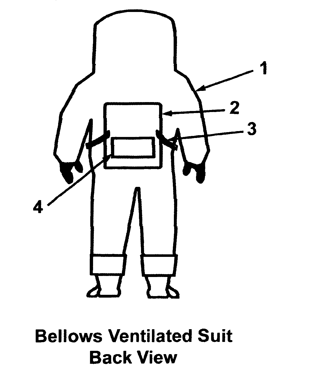
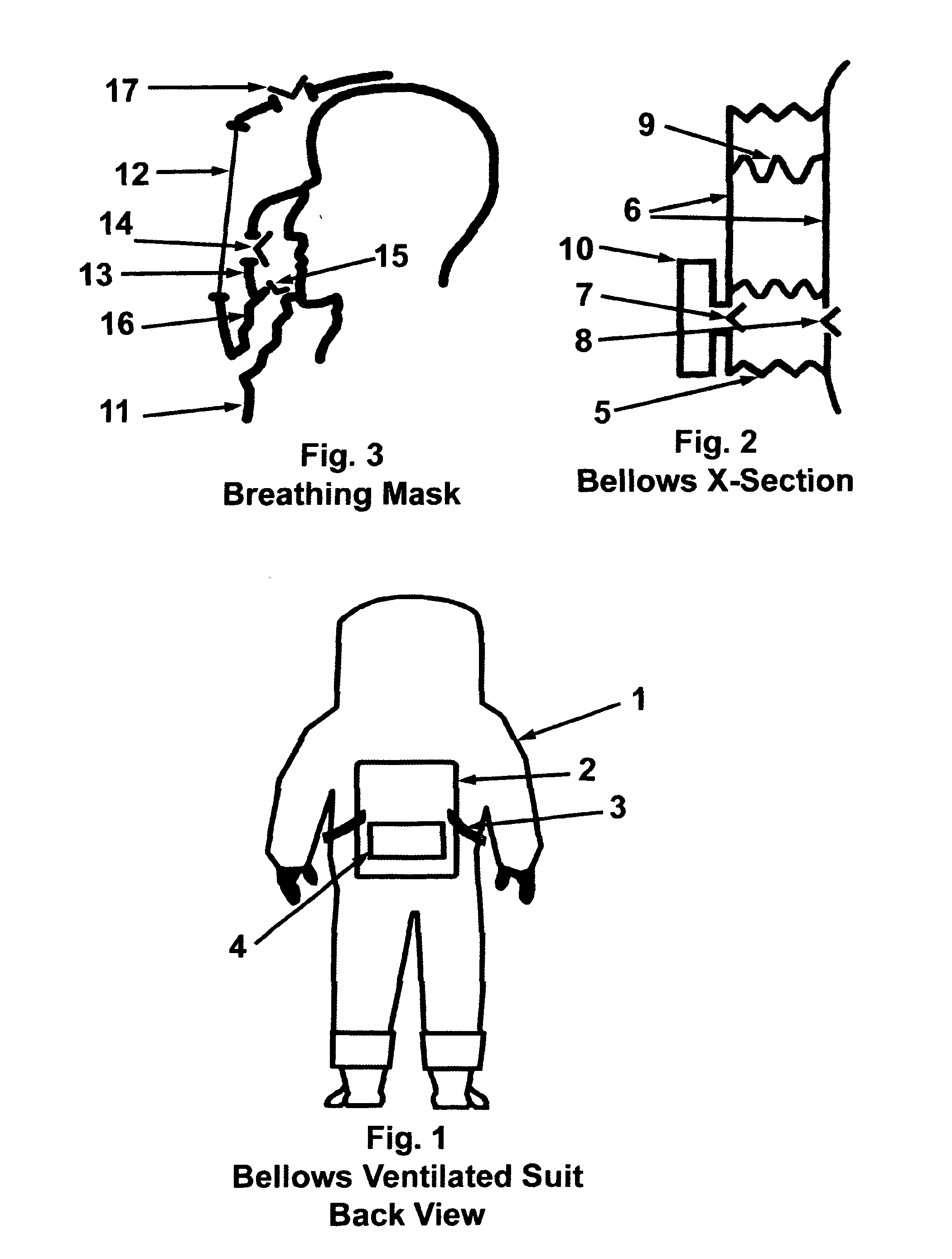
[0031]FIG. 1 is a rear view of the suit with the bellows attached to it's back. Item (1) is a protective suit. Item (2) is a bellows attached to the back of the suit. Items (3) are straps, attached to the bellows, which extend around the front of the suit. When the straps are pulled forward by the wearer, from the front of the suit, the bellows collapse, forcing air into the suit. When the straps are released, the bellows self-expands, drawing filtered air into the bellows. Item (4) is an air filter, attached to the bellows, which filters air entering the bellows.

[0032]FIG. 2 is a cross-sectional view of the Bellows. Item (5) is a flexible material forming the collapsible sides of the bellows. Items (6) are plates forming the front and back bases of the bellows. Item (7) is a one-way valve (also known as a check valve or automatic valve) which allows air to be drawn into the bellows when the bellows expands. Item (8) is a one-way valve which allows air to be forced into the suit's ...


PUM


Abstract

Protective suits are used to protect the wearer against hazardous materials such as particulates, liquids, chemicals, pathogens, radiation, electromagnetism, physical trauma, heat and for rain protection. They are used to protect the wearer's surrounding in cleanrooms. Medical protective suits are used to prevent the spread of pathogens from the wearer. Unfortunately, they can cause heat stress by reducing air circulation. This invention discloses a protective suit with bellows and dual one-way valves operated by the normal movement of the wearer to draw air through the suit's interior to cool the wearer and provide breathable air. Filters can be placed in the bellows and suit's air vents, or the suit can be made of a filter material to protect the wearer and the surroundings. The disclosed suit is lighter, less expensive and more mobile than prior-art protective ventilated suits that use powered or externally supplied ventilation and cooling devices. It does not depend on limited life portable power sources for ventilation. Filtered air, supplied by the bellows, can be used for breathing, eliminating the need for a separate source of air.

Description

CROSS REFERENCE TO RELATED APPLICATION [0001]“Ventilated Breathing Powered Protection Suit” specification submitted by Robert B. Steinert, Ser. No. 10 / 613,948, Filing Date Jul. 7, 2003, Customer Number 37498.FEDERALLY SPONSORED RESEARCH OR DEVELOPMENT [0002] Not Applicable. SEQUENCE LISTING [0003] Not Applicable. BACKGROUND OF THE INVENTION [0004] Protective suits are in wide use. They are designed to protect the wearer from Hazardous Materials (pathogens, chemicals, particulates, and radioactive contaminates). They are used to protect clean environments from potentially harmful sources from the wearer, such as particular contaminations in cleanrooms. They are used to protect people and animals from pathogens spread by the wearer such as in the surgical operating rooms of medical facilities and for the protection of laboratory animals, which must be pathogen free. They are used to protect workers from electrical, electromagnetic and radioactive sources. They are used for protection ...

Claims


Application Information

Patent Timeline
IPC IPC(8): A61M15/00A62B7/00A62B17/00A62D5/00
CPCA62B17/006A62B17/005
Inventor STEINERT, ROBERT B.
Owner KK TOSHIBA
Why Eureka
Try Eureka