
Method for manufacturing inkjet printing head

Active Publication Date: 2005-01-20
BROTHER KOGYO KK
View PDF8 Cites 4 Cited by
  • Summary
  • Abstract
  • Description
  • Claims
  • Application Information

AI Technical Summary

Benefits of technology

[0006] Therefore, one of objects of the invention is to provide a method for manufacturing an inkjet printing head in which even in the case where a common ink chamber is formed in the inside of the inkjet printing head, a plurality of metal plates located near to the common ink chamber can be fixed to one another by metal-metal junction surely.

Problems solved by technology

However, if such a predetermined pressure is applied in a bonding direction of the etching plates when a large-size ink flow path (common ink chamber) having a large opening is formed in the inside of the inkjet printing head, the etching plate laminated so as to be adjacent to the common ink chamber is insufficiently supported in the direction of application of the pressure by the layer forming the common ink chamber.
For this reason, it is impossible to obtain a sufficient bonding strength between the etching plate adjacent to the common ink chamber and another etching plate adjacent to the etching plate.
In addition, reliable metal-metal junction cannot be achieved because the size of other ink flow paths formed from these etching plates may be deformed.

Method used


Image

  • Method for manufacturing inkjet printing head
  • Method for manufacturing inkjet printing head
  • Method for manufacturing inkjet printing head

Examples


first embodiment

[0023] First Embodiment

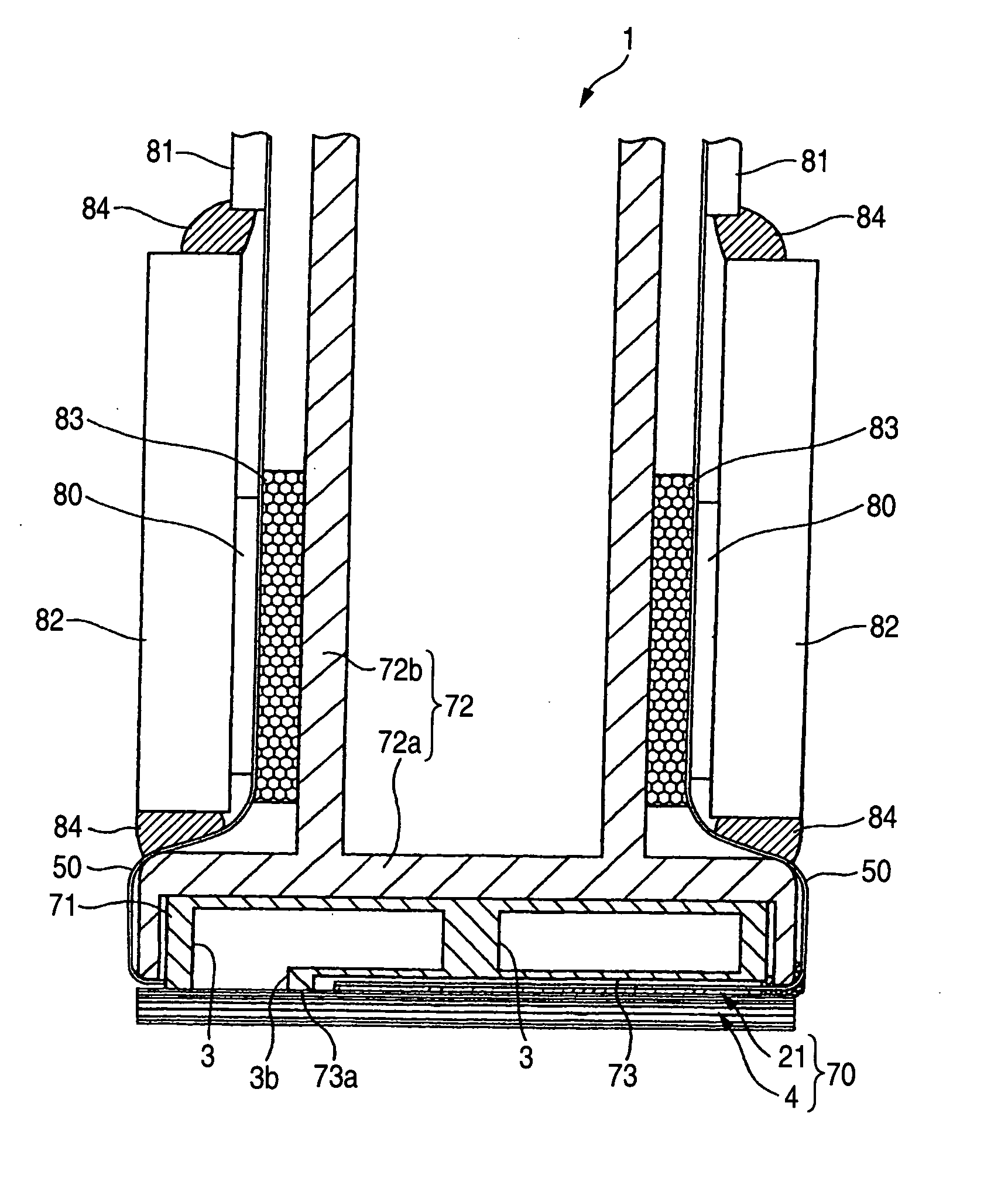
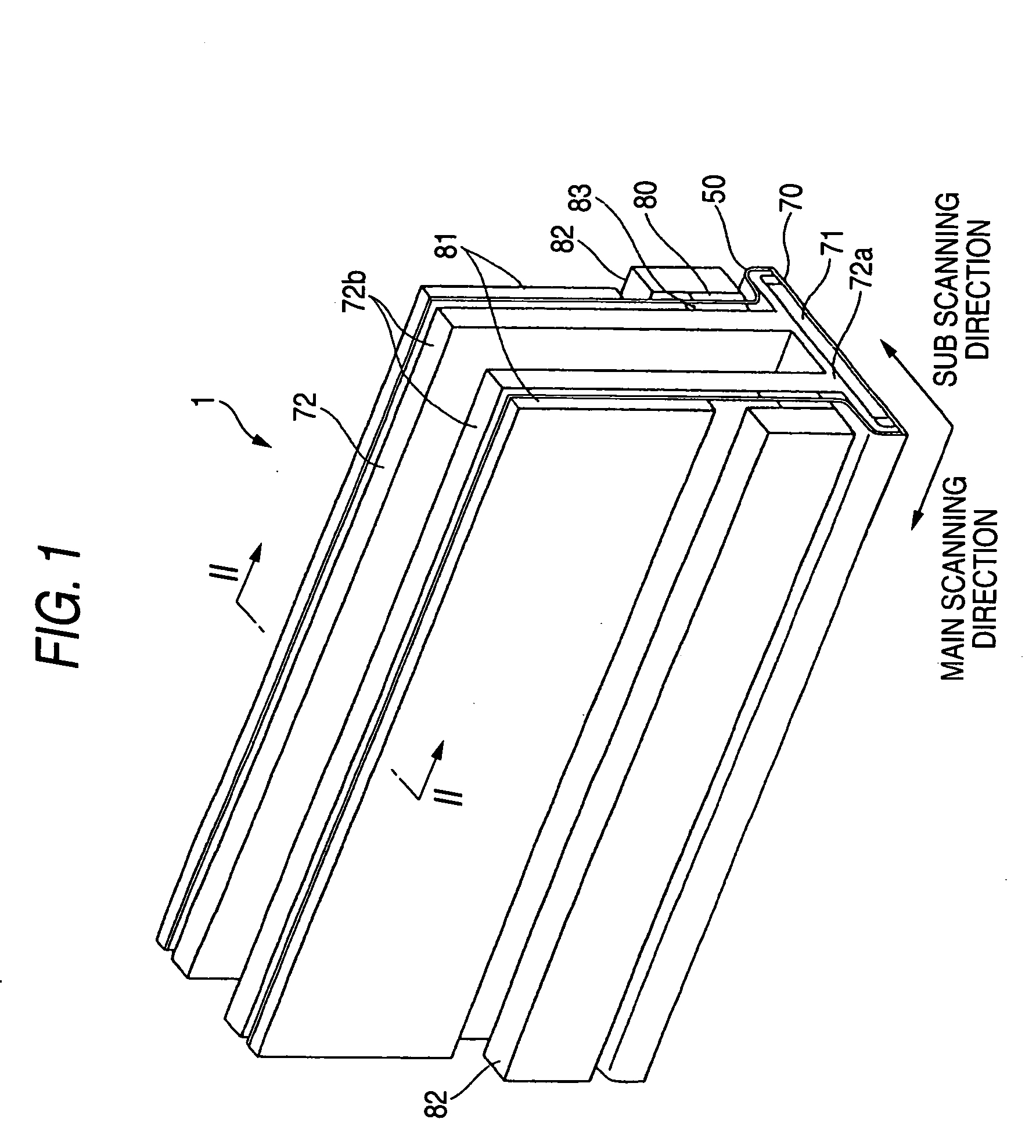
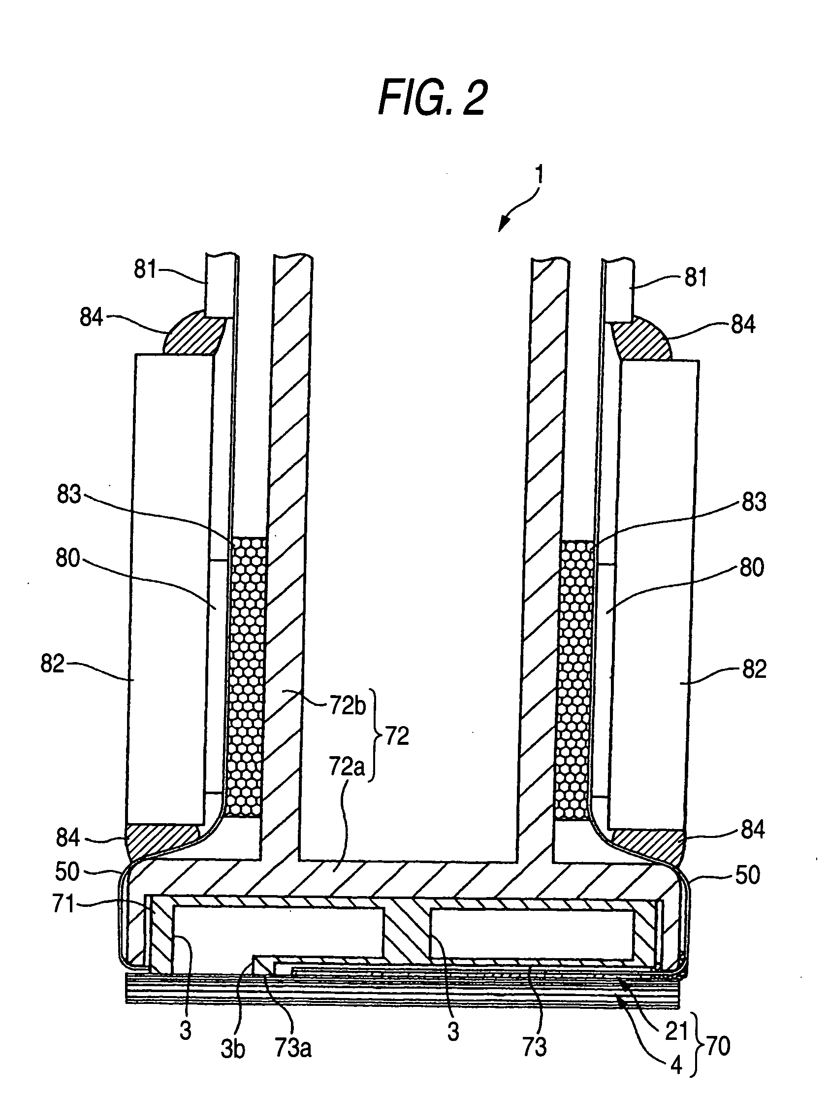
[0024] Hereinbelow, a description will be made of an ink-jet printing head 1, which is manufactured by a method according to a first embodiment. FIG. 1 is a perspective view showing the external appearance of an inkjet printing head according to a first embodiment. FIG. 2 is a sectional view taken along the line II-II in FIG. 1. The inkjet printing head 1 has a head body 70, and a base block 71. The head body 70 is shaped like a flat rectangle extending in a main scanning direction for ejecting ink onto a sheet of paper. The base block 71 is disposed above the head body 70 and includes ink reservoirs 3 formed as flow paths of ink supplied to the head body 70.

[0025] The head body 70 includes a flow path unit 4, and a plurality of actuator units 21. An ink flow path is formed in the flow path unit 4. The plurality of actuator units 21 are bonded onto an upper surface of the flow path unit 4. The flow path unit 4 and actuator units 21 are formed in such a manner...

second embodiment

[0059] Second Embodiment

[0060] A second embodiment of the invention will be described below with reference to the drawings.

[0061] The inkjet printing head manufactured by the ink-jet printing head manufacturing method according to the second embodiment is substantially the same as the inkjet printing head 1 manufactured by the inkjet printing head manufacturing method according to the first embodiment. The description of the ink-jet printing head manufactured by the inkjet printing head manufacturing method according to the second embodiment will be omitted.

[0062] A method for manufacturing the head body 70 will be described. The head body 70 is manufactured in such a manner that the actuator unit 21 and the flow path unit 4 are bonded to each other by an adhesive agent.

[0063]FIG. 11 is a block diagram showing steps for forming the flow path unit 4. FIG. 12 is a view for explaining the steps. As shown in FIGS. 11 and 12, the method of manufacturing an ink-jet printing head includ...


PUM

PropertyMeasurementUnit
Pressureaaaaaaaaaa
Adhesivityaaaaaaaaaa

Abstract

A method of manufacturing an ink jet printing head includes: forming a first laminated structure by laminating at least two metal plates having a hole formed thereon and fixing the metal plates to one another by metal-metal junction, and by laminating a plurality of thin plate members having a hole formed thereon, the thin plate members including the metal plates, and fixing the thin plate members to one another; forming a second laminated structure that includes at least a part of a common ink chamber, by laminating a plurality of thin plate members having a hole formed thereon and fixing the thin plate members to one another; and fixing the first laminated structure and the second laminated structure to each other while laminating the first laminated structure and the second laminated structure on each other.

Description

BACKGROUND OF THE INVENTION [0001] 1. Field of the Invention [0002] The present invention relates to a method for manufacturing an inkjet printing head for ejecting ink onto a recording medium to perform printing. [0003] 2. Description of the Related Art [0004] An inkjet printer includes at least one inkjet printing head having nozzles disposed therein so that ink can be ejected from the nozzles to apply printing onto a printing medium. In such an inkjet printing head, it is necessary to form complex and accurate ink flow paths in the inside of the inkjet printing head. Therefore, the inkjet printing head is formed by lamination of thin plate-like etching plates. To laminate and bond the etching plates on one another surely, for example, use of an adhesive agent such as an epoxy adhesive agent, a polyimide adhesive agent or an acrylic adhesive agent may be thought of. However, when the amount of the adhesive agent applied is large, the adhesive agent may flow into ink flow paths for...

Claims


Application Information

Patent Timeline
IPC IPC(8): B41J2/14B41J2/16
CPCB41J2/14209B41J2/1609B41J2/1623B41J2/1626B41J2002/14217B41J2002/14225Y10T29/49144B41J2002/14459B41J2202/20Y10T29/42Y10T29/49149Y10T29/49401B41J2002/14306
Inventor KANADA, HIDEKIAOKI, HIKOHARUSAKAIDA, ATSUOKOBAYASHI, KAZUOSUZUKI, YOSHIHUMI
Owner BROTHER KOGYO KK
Learn More