
Hollow plastic product having a connector pipe

Active Publication Date: 2005-04-21
EX CELL O CORP
View PDF6 Cites 2 Cited by
  • Summary
  • Abstract
  • Description
  • Claims
  • Application Information

AI Technical Summary

Benefits of technology

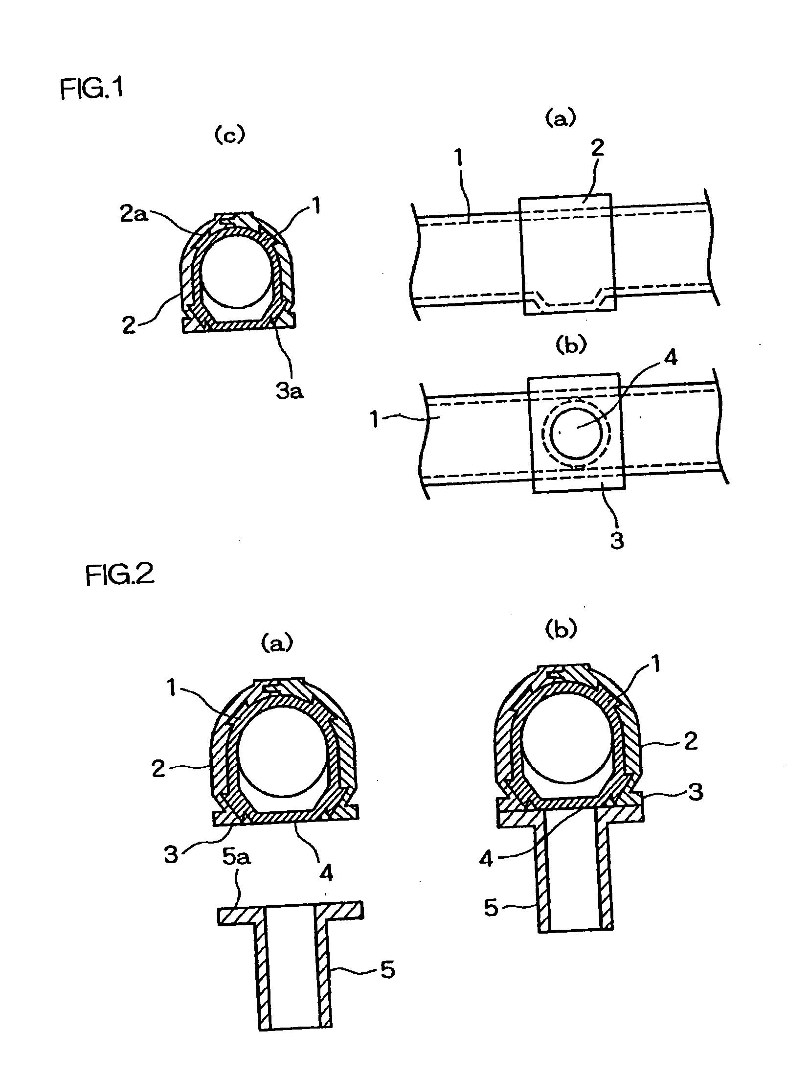
[0017] As an example, the clamp structure may be a combination of a dove-tail projection and a corresponding dove-tail notch which mate together. For example, a plurality of dove-tail projections may be provided at the outer surface of the hollow main body arranged spaced apart from each other around a circumference of the hollow main body, and a plurality of corresponding dove-tail notches may be provided at the inner surface of the reinforce member so that each dove-tail projection may mate or engage with the corresponding dove-tail notch, which allows to obtain an increased mechanical and intimate contact strength. Thus, even if the hollow main body is comprised of a soft rein material to provide some flexibility, the hollow main body may remain integrated with the reinforce member sufficiently.
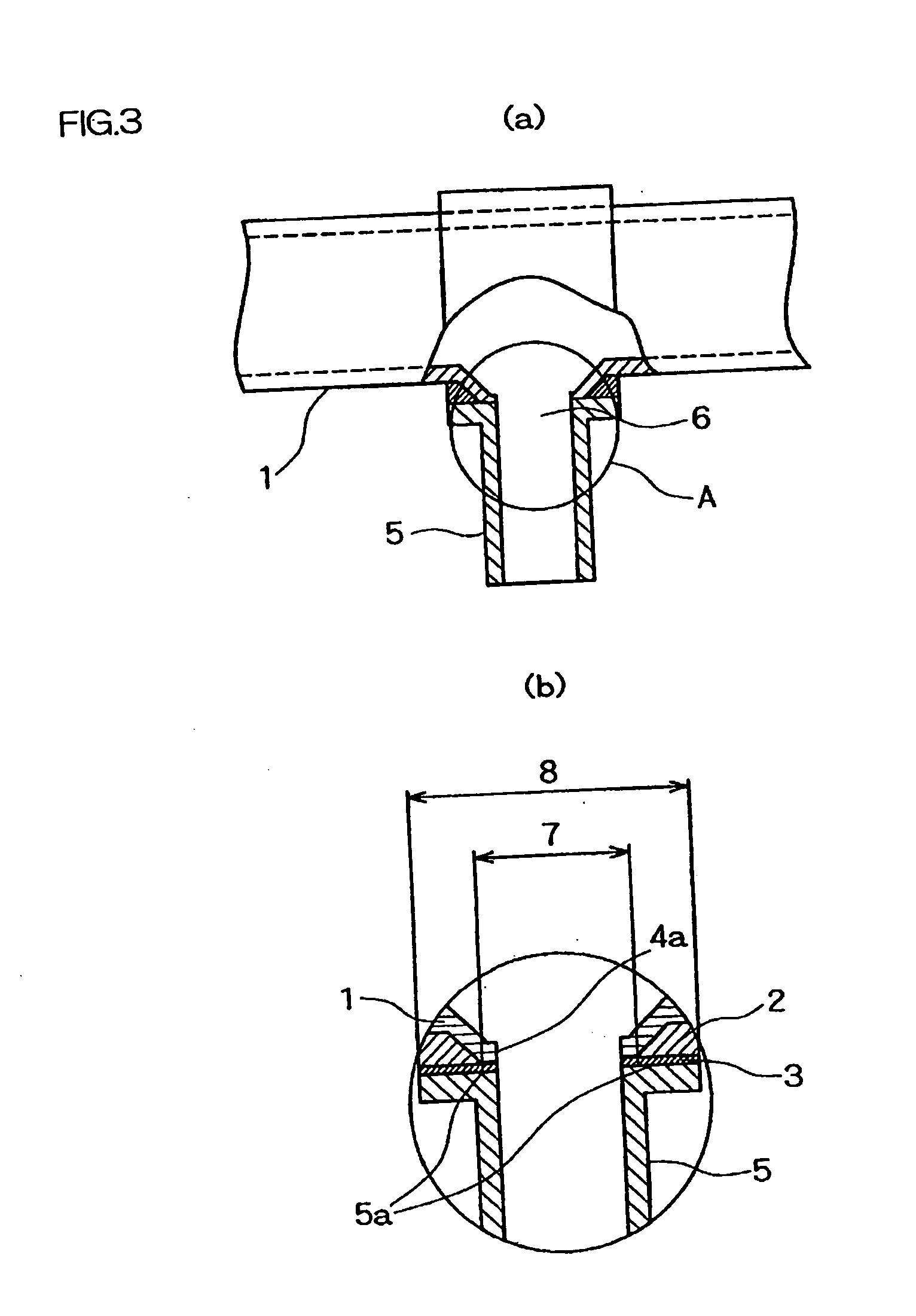
[0019] Furthermore, the reinforce member has an increased flexibility in design so as to obtain a sufficient bonding strength when welled to the connector pipe. If desired, the welding surface of the reinforce member may be so designed to be larger in size than the outer diameter of the hollow main body, so that a connector pipe large in diameter, that was not possible to be used in the past, can be used in the present invention.
[0020] As described above, in accordance with the present invention, there is provided a hollow plastic product, such as a duct, hose or pipe, by providing a hollow main body insert-molded with a reinforce member having a defined welding surface, thermally welding one end surface of a connector pipe to a portion of the welding surface and also a portion of the main body, and providing a through-hole extending between an interior of the hollow main body and an interior of the connector pipe. Because of the provision of the reinforce member having a defined welding surface, there is provided an increased flexibility in structure and design of a connector pipe, and, moreover, a connector pipe can be properly added or bonded to the main body even if the hollow main body is comprised of a soft resin material. Therefore, there is provided a hollow plastic product, such as a duct, hose or tube having a connector pipe excellent and high flexibility in design. More specifically, it is possible to obtain such advantages as increased bonding strength and air-tightness at a connection point between the main body and the connector pipe, an increased degree of freedom in structure and design of a connector pipe, and an increased degree of selection of a material for the main body and the connector pipe, in particular the allowability of using a soft resin material for the main body.
[0022] Another object of the present invention is to provide a hollow plastic product having a connector pipe which is sturdy and reliable in structure and easy to manufacture.

Problems solved by technology

In particular, in the case where the adherence provided by insert molding is poor and a required air-tightness cannot be attained, use was made of a method of welding a connector pipe to a blow-molded product.
In this manner, since such a blow-molded portion which has been increased in outer diameter becomes thinner, if, for example, a connector pipe is to be added to that portion by insert molding, the adherence strength of the insert becomes poor so that there is an increased chance for the insert to be disassembled, or, in some cases, the parison, when blown up, breaks to thereby form a hole.
In addition, in the case of adding a connector pipe by thermal welding, a thin portion of a blow-molded product may become so deformed due to the heat at a melting step of thermal welding that it is impossible to complete the thermal welding.
In this case, since use is made of a soft resin in forming a main body to be blow molded, if a connector pipe is to be added to such a flexible duct, hose or a tube, it will easily fall off because of poor adherence strength if added by insert molding, and thermal welding cannot be used because the flexible blow-molded main body would become softer and deform undesirably during the pressure bonding stage of thermal welding.
In such conventional methods as described above, if a connector pipe was added to a blow-molded hollow product of a duct, pipe or tube, in particular, both comparable in diameter, the portion of the product to which the connector pipe was added became thinner, so that such problems as reductions of adherence strength, formation of holes and incapability of using thermal welding were brought about.
The structure and size of a connector pipe to be added to a blow-molded hollow product was limited.
Moreover, in the case of a blow-molded duct, hose or tube having flexibility, since the main body of such a product was made of a soft resin, there was a disadvantage of poor adherence strength of a connector pipe when added and there was also a problem of incapability of using thermal welding because the main body became too soft when heat was added during thermal welding.
Thus, the material to be used for the main body was also limited.
Thus, the design of connector pipe 55 is limited and there is a case in which a desired product cannot be produced.
In addition, since the welding portion 33 of blow-molded hose 11 is defined by a portion where the parison is enlarged during a blow-molding process, it becomes thinner, which tends to make it difficult to carry out thermal welding properly.
Furthermore, if the blow-molded hose 11 is made of a soft resin material, there may be a case where thermal welding cannot be applied since the hose 11 may become too soft when heat is applied, thereby causing the hose to be deformed.

Method used


Image

  • Hollow plastic product having a connector pipe
  • Hollow plastic product having a connector pipe
  • Hollow plastic product having a connector pipe

Examples


Embodiment Construction

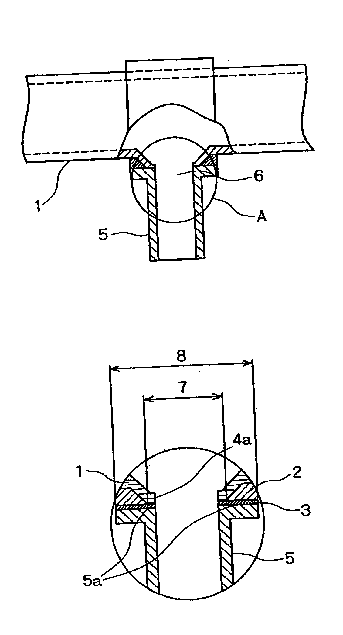
[0033] Referring now to FIGS. 1(a) and (b), there is schematically shown a hollow main body or hose 1 which is formed by blow molding. A reinforce member 2 formed by injection molding and generally in the shape of a ring is integrally provided on or added to the main body 1 by insert molding. The main body 1 is comprised of a first rein material and the reinforce material is comprised of a second rein material, which may be same as the first resin material. The reinforce member 2 may be integrally added to the main body 1, for example, by placing the reinforce member 2 in a mold when blow-molding the main body 1 in the mold. In this case, a parison placed in the mold becomes inflated by blow-molding so that the reinforce member 2 may be integrally added to the main body 1. The reinforce member 2 may be of a multi-segment structure, in which case the segments may be so structured to be integrated together when the main body 1 is blow-molded. Alternatively, the main body 1 alone may b...


PUM

PropertyMeasurementUnit
Lengthaaaaaaaaaa
Structureaaaaaaaaaa
Shapeaaaaaaaaaa

Abstract

A hollow plastic product including a hollow main body, a reinforce member and a connector pipe is provided. Such a hollow plastic product is, for example, used advantageously as a component of an air-intake system or fuel supply system of an automobile. In one example, the hollow main body is a duct, hose or tube extending over a length, and the reinforce member is ring-shaped so that it extends around a circumference of an outer surface of the hollow main body. The reinforce member is manufactured by injection molding and is used as an insert when blow-molding the hollow main body, so that the reinforce member is integrally formed with the main body. The reinforce member has a defined welding surface formed with a first hole, to which one end surface of a connector pipe is thermally welded. Then the hollow main body is formed with a second hole in alignment with the first hole, thereby defining a fluidic communication between the hollow main body and the connector pipe.

Description

BACKGROUND OF THE INVENTION [0001] 1. Field of the Invention [0002] This invention generally relates to a hollow plastic product and its manufacturing method, and, in particular, to a hollow plastic product having a connector pipe, which may be used as a duct, hose, tube or the like for flowing a gas, such as air, or liquid, such as water and its manufacturing method. In particular, a hollow plastic product of the present invention may be advantageously used as a duct, hose, tube or the like of an air intake system or a fuel supply system to be used in combination with an internal combustion engine of an automobile. [0003] 2. Description of the Prior Art [0004] Among the components of an air intake system of an automobile, blow molded products are used for ducts, hoses, tubes for introducing air into an internal combustion engine, a blowby hose for returning a blowby gas containing the oil components that are produced at the engine to these ducts, etc., and components for connecting...

Claims


Application Information

Patent Timeline
IPC IPC(8): F16L41/08B29C37/00B29C49/20B29C49/42B29C65/02B29C69/02B29D23/00B29L22/00F16L47/06F16L47/30
CPCB29C37/0082B29C66/53243B29C65/02B29C2049/2017B29C2049/206B29C2049/2069B29C2791/001B29C2793/0018B29D23/008B29K2023/12B29K2077/00B29K2105/06B29K2105/12B29K2709/08B29L2023/22B29L2031/246F16L47/30B29C49/20B29C66/5229B29C66/52241B29C66/532B29C65/00B29C66/112B29C66/131B29C66/71B29C66/7212B29C66/7392B29C66/8322B29K2309/08B29K2023/10B29K2067/006
Inventor NAKAGAWA, TATSUYAEZAKI, YASUO
Owner EX CELL O CORP
Learn More