
Hybrid vehicle controller

Inactive Publication Date: 2005-01-20
AISIN AW CO LTD
View PDF10 Cites 13 Cited by
  • Summary
  • Abstract
  • Description
  • Claims
  • Application Information

AI Technical Summary

Benefits of technology

[0008] Accordingly, it is an object of the invention to provide a control device for a hybridvehicle in which the above problems are solved by properly controlling the motor speed when cars are braked during creeping by rotating only a motor after stopping with an idling stop function, thereby avoiding the uncomfortable shock, which could easily occur, as soon as possible.
[0011] Accordingly, when the braking state is detected while the motor is being rotated at an idling rotational speed or more, the motor control means controls the motor rotational speed to a predetermined rotational speed less than the idling rotational speed, eliminating a shock at the time of switching from static friction of the motor to dynamic friction which tends to generate every time the brake is released or applied during creeping, thus improving drive feeling. Driving at a rotational speed lower than the idling rotational speed at the time of braking leads to efficient reduction in power consumption.
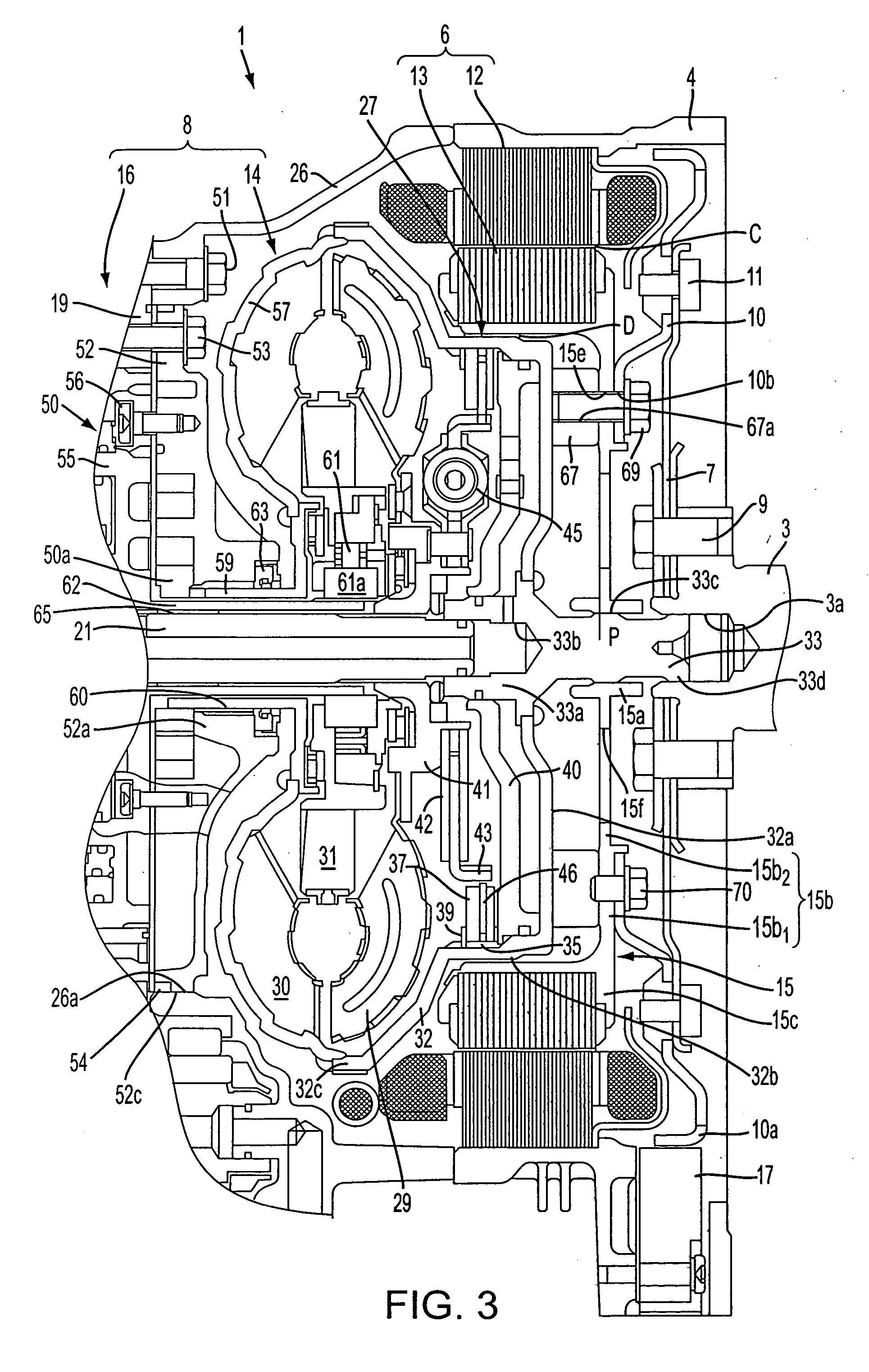
[0013] Further, because the rotor is directly connected to an output shaft of the engine, the engine output shaft can be rotated stably by the rotation of the motor to start the engine, thereby reducing, as much as possible, the vibrations of the engine and its mount which tend to generate at the time of engine startup.
[0015] Because the predetermined rotational speed is less than the idling rotational speed and larger than the engine resonance rotational speed, uncomfortable shock that tends to easily occur at the time of start and stop during creep running can be reduced as much as possible by controlling the motor rotational speed not to pass through the range of the engine resonance rotational speed every time the motor rotational speed decreases, thus improving drive feeling.
[0016] The motor control means stops the motor rotating at the predetermined rotational speed at the point in time when a predetermined time has elapsed from the start of the braking. Because the motor rotating at a predetermined rotational speed is stopped at the point in time when the time from the start of braking has elapsed, i.e., exceeds a predetermined time, it can be determined from the braking elapsed time that a driver desires to stop the car not intermittently but completely preventing creeping, and the motor can be stopped on the basis of the determination. Thus, unnecessary rotation of the motor can be prevented and power consumption can be reduced.
[0018] Accordingly, when the brake control input determined by the control-input determination means is less than a predetermined value at the time of detection of the braking state by the brake-operating-state detecting means, the motor control means can control the motor not to switch to the predetermined rotational speed to maintain the idling rotational speed. Therefore, for example, when the braking control input is less than 50 percent, the idling rotational speed can be maintained while regarding it as a state in which creeping by the motor is desired; on the other hand, when the depression amount exceeds 50 percent, the rotational speed can be switched to the predetermined rotational speed while regarding it as a state in which a temporary stop is desired. In this way, accurate motor drive control can be performed while determining the driver's intention depending on the difference in brake depression amount.

Problems solved by technology

With the above-described hybrid-car driving units, when the motor generator repeats the stop and the rotation by repeating the depression and release of the brake pedal (ON and OFF of the brake), uncomfortable shock occurs and is applied to a driver each time.

Method used


Image

  • Hybrid vehicle controller
  • Hybrid vehicle controller
  • Hybrid vehicle controller

Examples


Embodiment Construction

[0030] A first example will now be described.

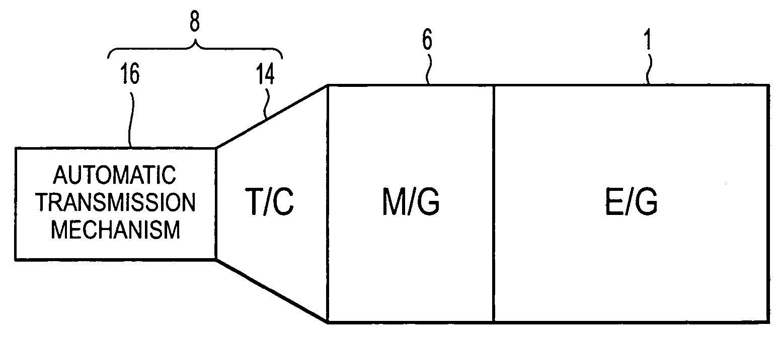
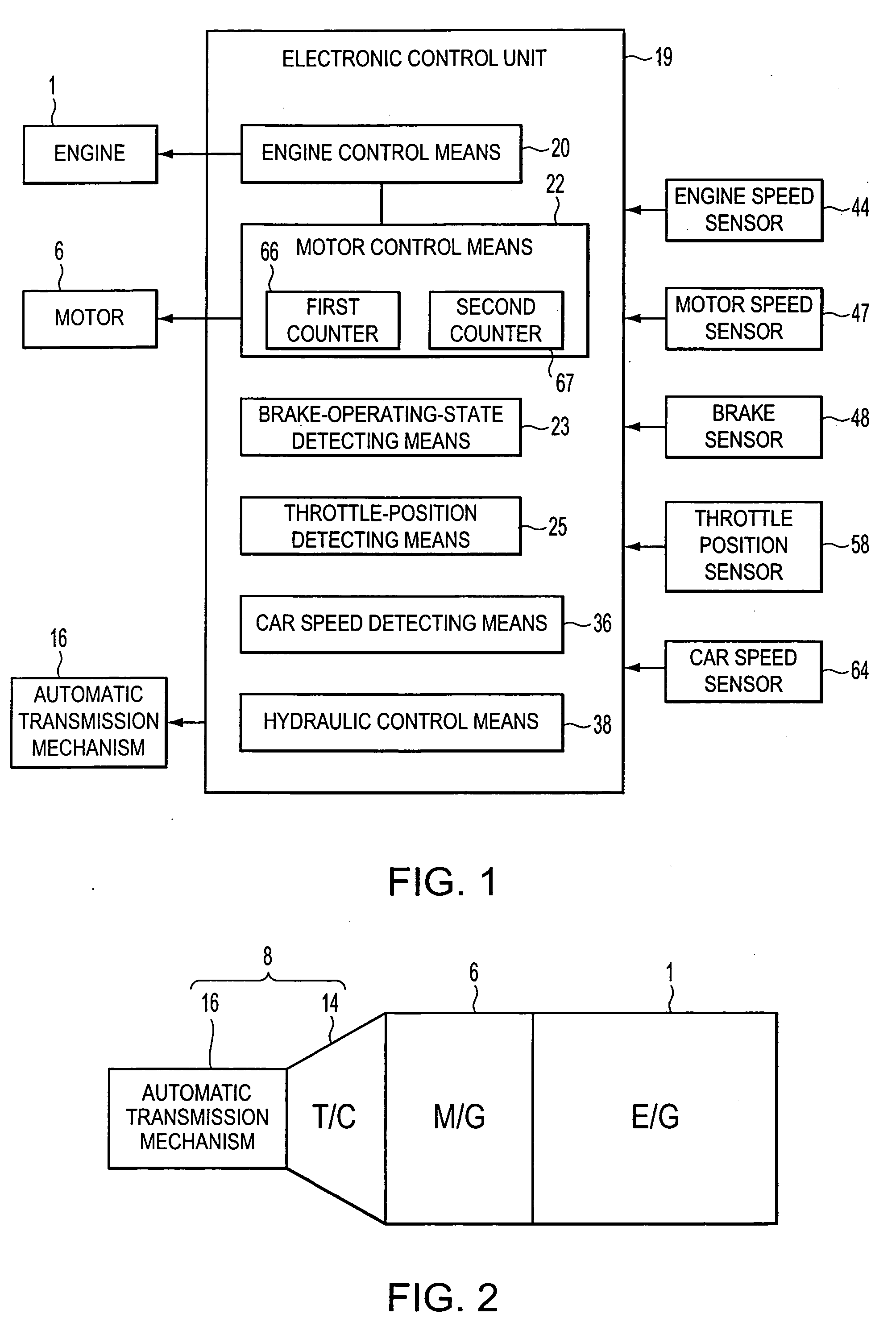
[0031] Referring to FIG. 2, the primary drive of the hybrid car includes an internal combustion engine (hereinafter, referred to as an engine) 1 and a motor generator (hereinafter, referred to as a motor) 6. Their driving forces are outputted to an automatic transmission 8. The automatic transmission 8 includes a torque converter (starting unit) 14 that transmits the driving forces of the engine 1 and the motor 6 to downstream power transmission components and allows rotation of a rotor 13 of the motor 6 when the driving wheels are braked and an automatic transmission mechanism (multistep transmission mechanism) 16. The automatic transmission mechanism 16 varies the inputted driving force depending on a predetermined car driving condition and outputs it to the driving wheels. The automatic transmission mechanism 16 includes a plurality of frictional engaging elements (not shown) for gear change and a hydraulic controller (not shown) for ...


PUM


Abstract

The controller includes motor control means for controlling the drive RPM of a motor generator to reach a specified RPM less than the idle RPM when the braking condition of a foot brake is detected by a brake-operating-state detecting means while a motor generator is being rotated at an idle RPM or more. This reduces uncomfortable shock which tends to occur because of a change in the rotation of the motor during braking as much as possible to improve drive feeling.

Description

[0001] This application is the U.S. National Stage of PCT / JP2003 / 010107 filed Aug. 8, 2003 which claims priority from JP2002-234007 filed Aug. 9, 2002, the disclosures of which are incorporated herein in their entireties by reference thereto.BACKGROUND OF THE INVENTION [0002] 1. Field of the Invention [0003] The invention relates to a hybrid vehicle controller having an idling stop function and, more particularly, it relates to a control device for a hybrid vehicle capable of avoiding a shock which tends to occur between braking and starting during motor single running. [0004] 2. Description of Related Art [0005] For hybrid cars including an internal combustion engine (hereinafter, referred to as an engine) and a motor generator (hereinafter, referred to as a motor) as the primary drive, particularly, hybrid cars having a so-called idling stop function of stopping an engine and a motor every time an accelerator pedal is released and a brake pedal (service brake (foot brake)) is depr...

Claims


Application Information

Patent Timeline
IPC IPC(8): B60K6/485B60W20/00B60K6/54B60L50/16B60T8/00B60W10/06B60W10/08B60W10/18F02D17/00F02D29/02F02D29/06F02N11/04F02N15/00
CPCB60K6/40B60K6/485Y02T10/6226B60W2540/12B60W10/08Y02T10/62
Inventor TAJIMA, YOICHIMURASE, YOSHITAKAKAYUKAWA, ATSUSHINAKAMORI, YUKINORIKOBAYASHI, YASUHIKO
Owner AISIN AW CO LTD
Learn More