Scanning apparatus having a fluorescent lamp and control method thereof

a fluorescent lamp and scanning apparatus technology, applied in the direction of electric variable regulation, process and machine control, instruments, etc., can solve the problems of reducing the lifetime of fluorescent lamps, unable to adjust the luminous intensity of fluorescent lamps, and high power consumption, so as to prolong the lifespan of fluorescent lamps and low power consumption

Inactive Publication Date: 2005-01-20
SAMSUNG ELECTRONICS CO LTD
View PDF9 Cites 22 Cited by
  • Summary
  • Abstract
  • Description
  • Claims
  • Application Information

AI Technical Summary

Benefits of technology

[0009] Accordingly, the present invention has been made to solve the above-mentioned and / or other problems, and an aspect of the present invention is to provide a scanning apparatus having a fluorescent lamp of low power consumption therein and capable of prolonging the lifespan of the fluorescent lamp by variably applying electricity in accordance with the respective operation modes of the scanning apparatus, and a control method thereof.

Problems solved by technology

Consequently, the conventional fluorescent lamp controlling apparatus can not variably control the voltage applied to the fluorescent lamp and therefore, cannot adjust the luminous intensity of the fluorescent lamp for the respective operation modes of the scanning apparatus.
Additionally, the conventional fluorescent lamp takes a long time to initially operate the fluorescent lamp because of the longer initial preheating time thereof, reducing the fluorescent lamp's lifetime, and causing higher power consumption.

Method used


Image

  • Scanning apparatus having a fluorescent lamp and control method thereof
  • Scanning apparatus having a fluorescent lamp and control method thereof
  • Scanning apparatus having a fluorescent lamp and control method thereof

Examples


Embodiment Construction

[0024] Reference will now be made in detail to the embodiments of the present invention, examples of which are illustrated in the accompanying drawings, wherein like reference numerals refer to the like elements throughout. The embodiments are described below in order to explain the present invention by referring to the figures.

[0025] Hereinafter, the description will be made as to an embodiment of the present invention with reference to FIG. 2. In the following description of the present invention, a detailed description of known functions and configurations incorporated herein will be omitted when it may make the subject matter of the present invention rather unclear.

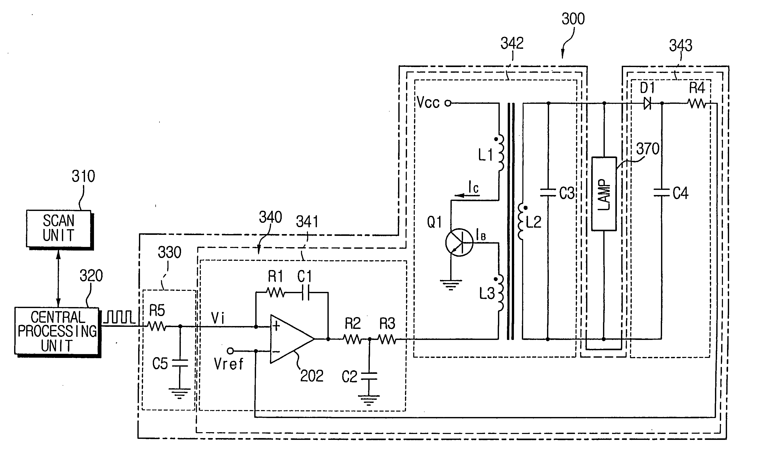
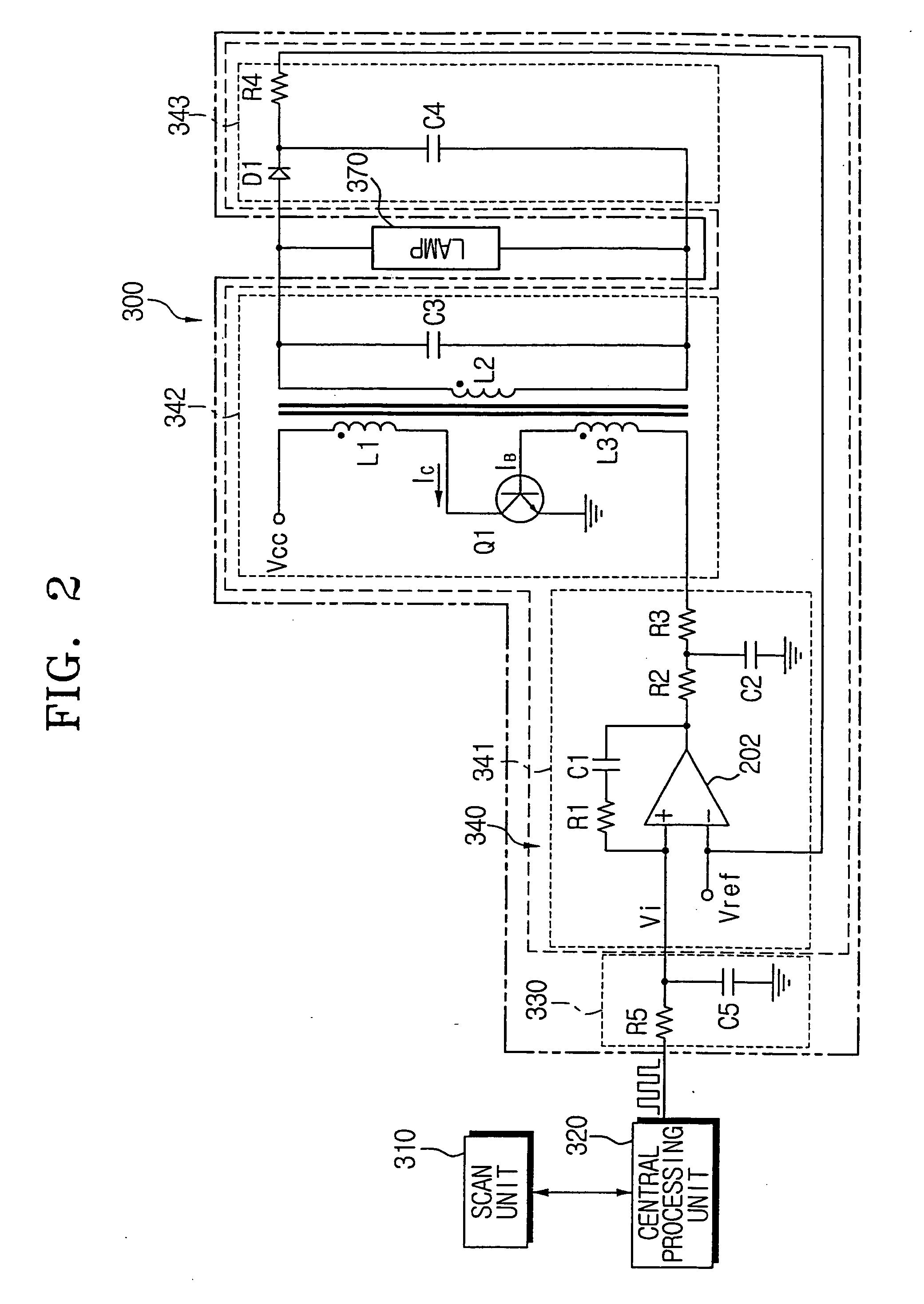
[0026]FIG. 2 is a circuit diagram illustrating a scanning apparatus having a fluorescent lamp according to an embodiment of the present invention.

[0027] As shown in FIG. 2, the scanning apparatus having the fluorescent lamp includes a scan unit 310, a central processing unit (CPU) 320, a fluorescent lamp 370 and a ...


PUM


Abstract

A scanning apparatus having a cold cathode fluorescent lamp includes a central processing unit (CPU) controlling a scan unit to be in one of the stand-by mode, a scan mode and a sleep mode and outputting a PWM signal having a variable duty ratio based on an operation mode of the scan unit; a filter unit receiving the PWM signal from the CPU, filtering the PWM signal, and outputting the filtered signal; a feedback unit detecting the voltage applied to the fluorescent lamp and outputting a feedback signal; a controlling unit controlling the illumination of the fluorescent lamp based on the voltage input from the feedback unit, the controlling unit outputting a control signal variably controlling the voltage applied to the fluorescent lamp depending on the filtered signal; and a lamp drive unit applying variable AC voltage to the fluorescent lamp based on the control signal, thereby driving the fluorescent lamp. Accordingly, it is possible to control the luminous-intensity of the fluorescent lamp, reduce preheating time of the fluorescent lamp, extending the fluorescent lamp's lifetime, and lowering the power consumption.

Description

CROSS-REFERENCE TO RELATED APPLICATIONS [0001] This application is a continuation-in-part of prior U.S. patent application No. 10 / 443,064 filed on May 22, 2003. This application claims the benefit of Korean Patent Application No. 2002-40104, filed Jul. 10, 2002 in the Korean Intellectual Property Office, the disclosure of which is incorporated herein by reference.BACKGROUND OF THE INVENTION [0002] 1. Field of the Invention [0003] The present invention relates to a scanning apparatus employing therein an apparatus controlling a fluorescent lamp, and more particularly, to a scanning apparatus variably controlling a luminous intensity of a fluorescent lamp and a control method thereof. [0004] 2. Description of the Related Art [0005] The cold cathode fluorescent lamp is widely utilized as a backlight source to illuminate the display panel of a liquid crystal display used as a display, such as in a portable notebook computer and the like, or as a light source constantly illuminating a ma...

Claims


Application Information

Patent Timeline
Patent Type & Authority Applications(United States)
IPC IPC(8): H05B41/282H05B41/392
CPCH05B41/392H05B41/2821
Inventor RYU, HAN-CHUNGCHOO, JONG-YANG
Owner SAMSUNG ELECTRONICS CO LTD
Why Eureka
Try Eureka