Seesaw-type MEMS switch for radio frequency and method for manufacturing the same

a technology of mems switch and radio frequency, which is applied in the direction of relays, generators/motors, and snap-action arrangements, etc., can solve the problems of inability to the contact point is permanently stuck, and the method cannot additionally avoid the second type occurrence, etc., to prevent the deformation of the structure and the effect of reducing the driving voltag

Active Publication Date: 2005-01-20
SAMSUNG ELECTRONICS CO LTD
View PDF6 Cites 7 Cited by
  • Summary
  • Abstract
  • Description
  • Claims
  • Application Information

AI Technical Summary

Benefits of technology

[0013] Accordingly, in an effort to solve the above-described problems, it is a feature of an embodiment of the present invention to provide a seesaw-type MEMS switch for RF that can be driven by a low driving voltage and prevent deterioration in RF properties.
[0025] The MEMS switch for RF having the above-described construction, in which the intermittent part and the driving part are separated from each other so that interaction between the respective electrodes and the contact point may be controlled, can control stiction by means of the areas of the electrodes and minimize the driving voltage since it can be restituted simultaneously with the removal of the driving voltage applied to the lower electrode. Further, by using the seesaw movement, it is possible to prevent deformation of the structure when used for an extended period of time.

Problems solved by technology

However, this MEMS switch for RF also has a problem in that it requires a high driving voltage since it uses an electrostatic force and a stiction, i.e., static friction, phenomenon may occur at a contact point.
The stiction phenomenon describes an unintended and undesirable adhesion that occurs on a surface of a microstructure when a restitution force does not overcome interfacial forces, such as a capillary force, a van der Waals force, an electrostatic attraction, and the like, thus causing the contact point to become stuck, either permanently or for an unwanted period of time.
However, these methods cannot additionally avoid occurrence of the second type, the in-use stiction, in which a microstructure is not restored due to humidity or an excessive impact generated while in use.
This occurs because when surfaces of adjacent microstructures contact each other, a capillary force, an electrostatic attraction, a van der Waals force, or the like, are also generated and surface adhesion may occur due to these forces, whereby stiction of the structure takes place, causing damage to a device.
However, the SAM method has several disadvantages, e.g., requiring complex treatment procedures, a significant cost of production, and a high dependency on temperature.
However, this conventional MEMS switch for RF has a problem in that the driving voltage necessary to move the cantilever beam 20 is increased.
For this reason, conventional MEMS-type switches have a driving voltage exceeding 10 V. Consequently, such a high driving voltage of a MEMS switch for RF requires a separate circuit for increasing the voltage, which contributes to an increase in cost, since general portable terminals are normally driven at a voltage as low as 3 V.
However, in a case like a switch, the time when the state conversion occurs is not regular and a duration of a state may be relatively long.
That is, in a case of a bridge-type or cantilever-type MEMS switch for RF, since a state changing part always receives one type of stress, such as N-T-N (Neutral-Tension-Neutral) or N-C-N (Neutral-Compressive-Neutral), except during the initial state, it cannot be restituted to the original state when used for a long period of time, which causes deterioration in RF properties.

Method used


Image

  • Seesaw-type MEMS switch for radio frequency and method for manufacturing the same
  • Seesaw-type MEMS switch for radio frequency and method for manufacturing the same
  • Seesaw-type MEMS switch for radio frequency and method for manufacturing the same

Examples


Embodiment Construction

[0033] Korean Application No. 2003-37285, filed Jun. 10, 2003, and entitled: “Seesaw-type MEMS Switch for Radio Frequency and Method for Manufacturing the Same,” is incorporated by reference herein in its entirety.

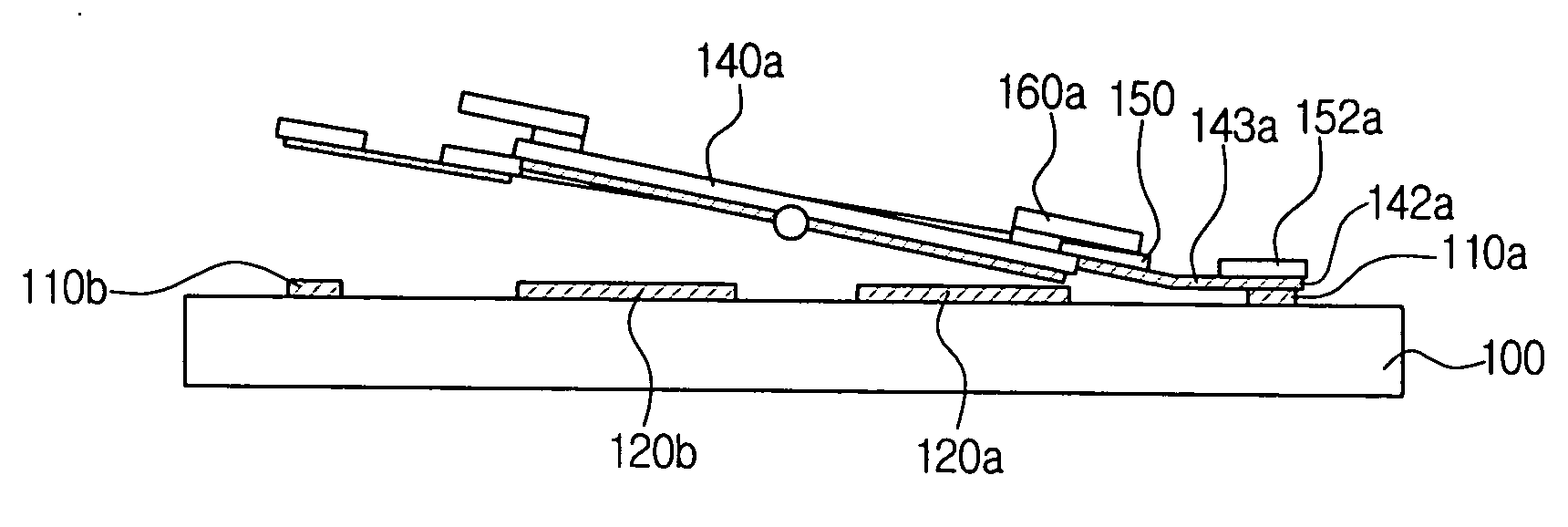
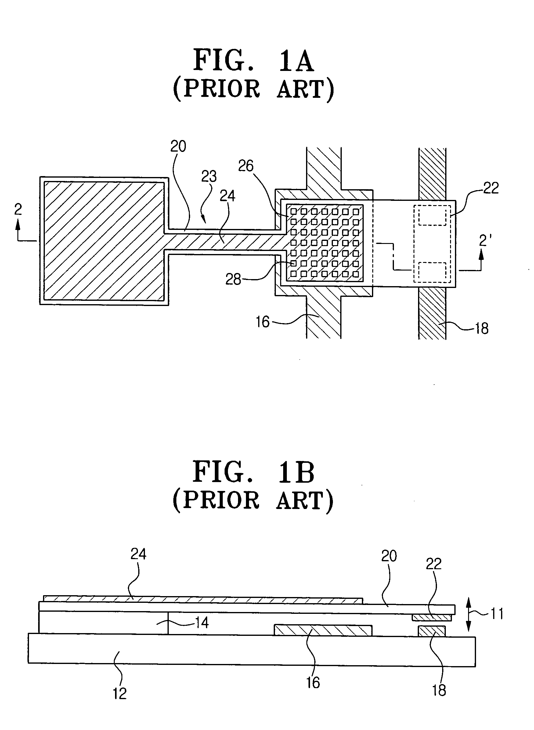
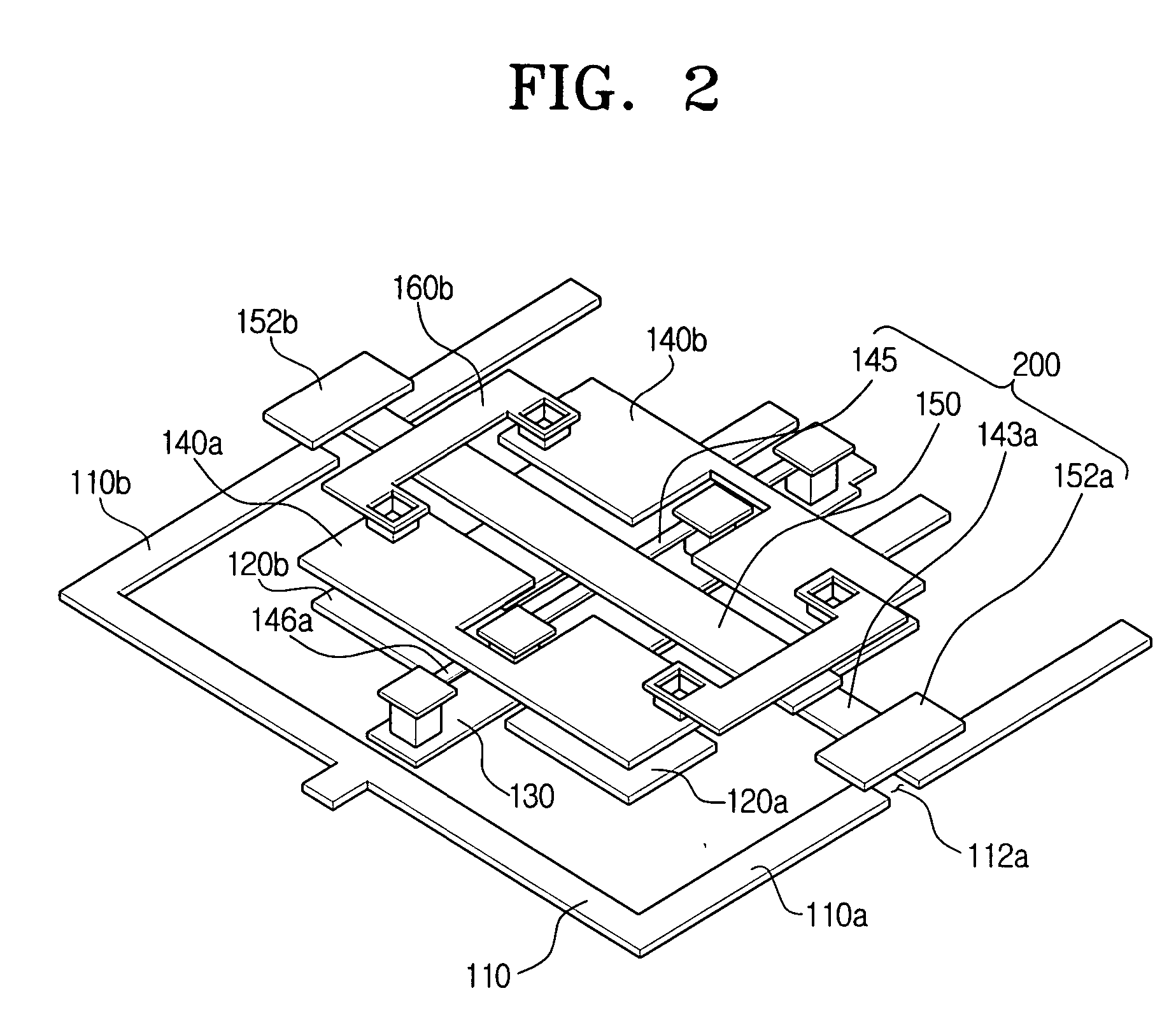
[0034] The present invention will now be described more fully hereinafter with reference to the accompanying drawings, in which preferred embodiments of the invention are shown. The invention may, however, be embodied in different forms and should not be construed as limited to the embodiments set forth herein. Rather, these embodiments are provided so that this disclosure will be thorough and complete, and will fully convey the scope of the invention to those skilled in the art. It will also be understood that when a layer is referred to as being “on” another layer or substrate, it can be directly on the other layer or substrate, or intervening layers may also be present. In addition, it will be understood that when a layer is referred to as being “between” two layers, i...


PUM

PropertyMeasurementUnit
frequencyaaaaaaaaaa
voltageaaaaaaaaaa
voltageaaaaaaaaaa

Abstract

In a seesaw-type MEMS switch for radio frequency (RF) and a method for manufacturing the same, the seesaw-type MEMS switch for radio frequency (RF) includes a substrate, a transmission line formed on the substrate having a gap therein to provide a circuit open condition, an intermittent part formed a predetermined distance from the substrate, the intermittent part being operable to contact the transmission line on both sides of the gap by performing a seesaw movement about a seesaw movement axis, and a driving part to drive the seesaw movement of the intermittent part in response to a driving signal.

Description

BACKGROUND OF THE INVENTION [0001] 1. Field of the Invention [0002] The present invention generally relates to a MEMS (Micro Electro Mechanical System) for RF (Radio Frequency). More particularly, the present invention relates to a MEMS switch for RF that can be driven at a low voltage and a method for manufacturing the same. [0003] 2. Description of the Related Art [0004] Generally, MEMS is a micro electro mechanical system that is manufactured using a semiconductor process. Recently, MEMS has been the focus of increased attention as a range of applications of MEMS technology has increased in connection with the development of mobile communication technology. Among such MEMS applications, a gyroscope, an acceleration sensor, an RF switch, and the like are being applied to products. In addition, the development of various other MEMS products has accelerated. [0005] A MEMS RF switch is embodied to switch a signal when a micro-sized MEMS structure on a semiconductor substrate moves to...

Claims


Application Information

Patent Timeline
Patent Type & Authority Applications(United States)
IPC IPC(8): B81B5/00B81C1/00H01H59/00H01P1/12
CPCH01H59/0009H01P1/127H01H2059/0054H01H59/00
Inventor SHIN, HYUNG-JAE
Owner SAMSUNG ELECTRONICS CO LTD
Why Eureka
Try Eureka