Cathode ray tube and method for manufacturing the same

a technology of cathode ray tube and manufacturing method, which is applied in the direction of discharge tube main electrodes, television system scanning details, television systems, etc., can solve the problems of insufficient elasticity of coils, damage of insulating layer of heaters, and inconventional heaters, so as to improve the quality and welding reliability of heaters, reduce the quantity of coils required and time required, and high efficiency heating

Inactive Publication Date: 2005-01-20
LG PHILIPS DISPLAY KOREA CO LTD
View PDF4 Cites 1 Cited by
  • Summary
  • Abstract
  • Description
  • Claims
  • Application Information

AI Technical Summary

Benefits of technology

[0024] An object of the present invention is to provide a cathode ray tube including an electron gun having a high efficiency heater, which can improve the quality and welding reliability of the heater and reduce the quantity of coil required and time required for winding the coil while accomplishing high efficiency heating.
[0027] The present invention can improve the quality and welding reliability of the heater and reduce the quantity of coil required and time required for winding the coil while accomplishing high efficiency heating. Accordingly, manufacturing cost and time are minimized and reliability of the cathode ray tube is improved.

Problems solved by technology

However, the conventional heater has the following problems.
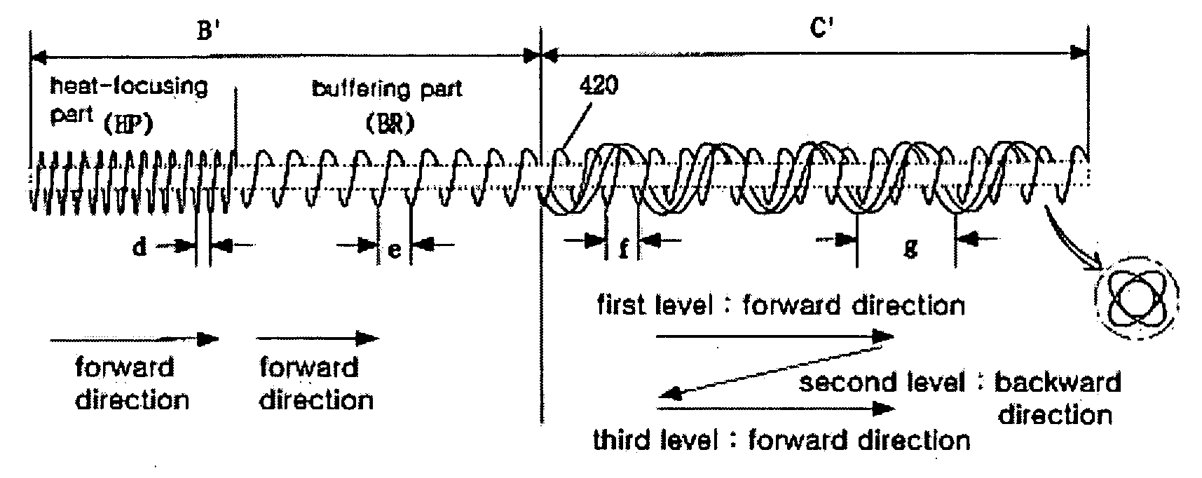
Firstly, the coil 420 of the heat-emitting part B and triple coil part C is wound very tightly so that the coil has insufficient elasticity.
Accordingly, the insulating layer of the heater is destroyed due to external shocks given to the heater and thermal expansion / contraction of the coil caused by power on / off.
Furthermore, although the heat-emitting part B has a small coil pitch to accomplish the high-efficiency heater, the quantity of coil 420 required is increased to result in cost increase and productivity deterioration.

Method used


Image

  • Cathode ray tube and method for manufacturing the same
  • Cathode ray tube and method for manufacturing the same
  • Cathode ray tube and method for manufacturing the same

Examples


Embodiment Construction

[0036] Preferred embodiments of the present invention will be described in a more detailed manner with reference to the drawings.

[0037] According to claim 1 of the present invention, there is provided a plasma display panel having a plurality of discharge cells, including barrier ribs by which a discharge space is defined between an upper substrate and a lower substrate; and an oxide film of a low dielectric constant formed on each of the barrier ribs.

[0038] According to claim 2 of the present invention, the oxide film of the plasma display panel as claimed in claim 1 comprises at least one of silicon oxide and magnesium oxide.

[0039] According to claim 3 of the present invention, the plasma display panel as claimed in claim 1 further comprises: a first electrode formed on the underside of the upper substrate; and a second electrode formed on the underside of the upper substrate in such a manner as to extend over the first electrode.

[0040] According to claim 4 of the present inve...


PUM


Abstract

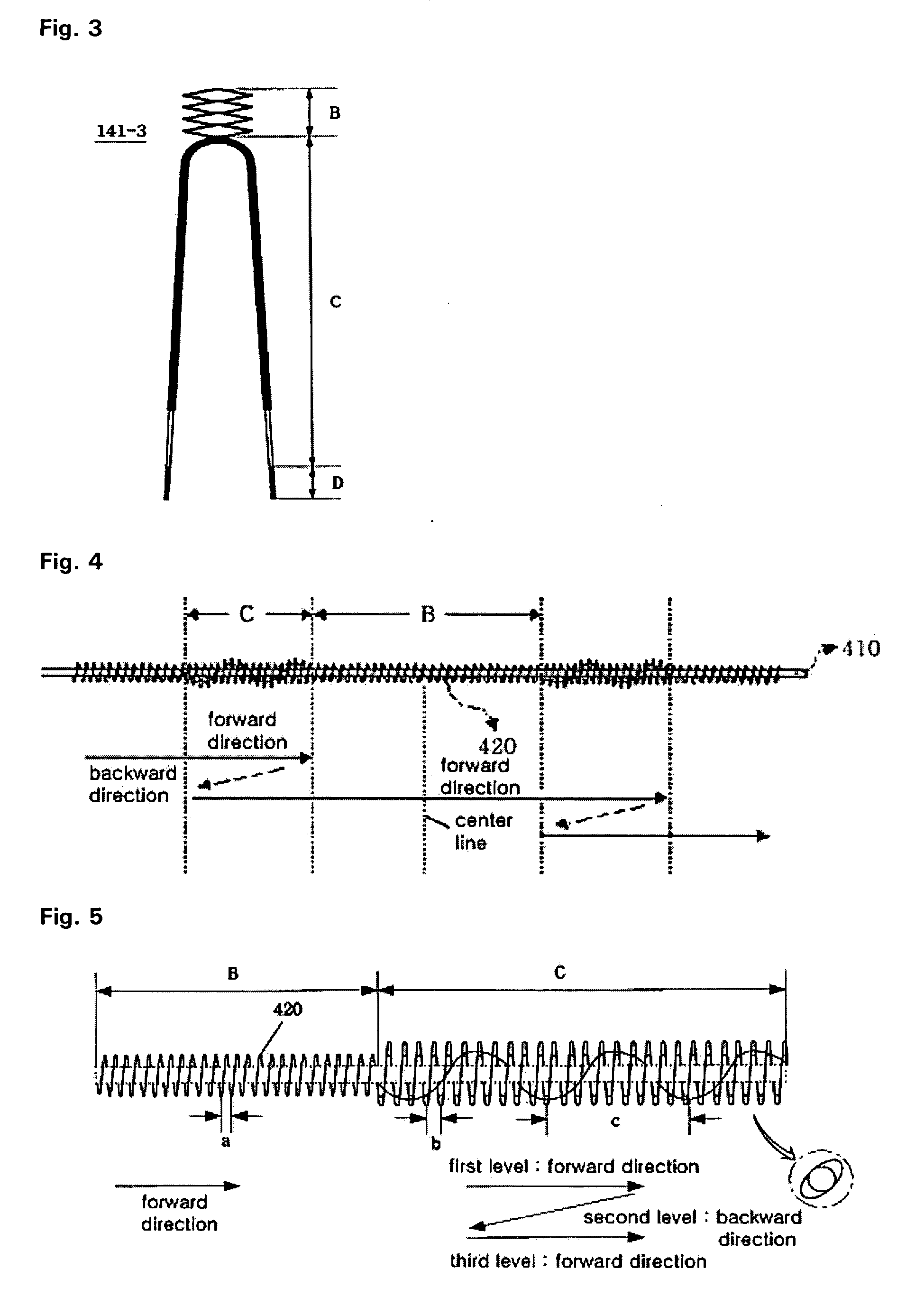
The present invention discloses a cathode ray tube including an electron gun having a heater and a method for manufacturing the same. The heater is formed using a coil and includes a heat-emitting part having a heat-focusing part on which heat generated from the coil is focused and a buffering part for buffering shocks, and a triple coil part formed such that the coil is wound in three levels at predetermined pitches. The pitches of second and third levels of the triple coil part are substantially identical to each other and larger than the pitch of the first level. The present invention can improve the quality and welding reliability of the heater and reduce the quantity of coil required and time required for winding the coil while accomplishing high efficiency heating.

Description

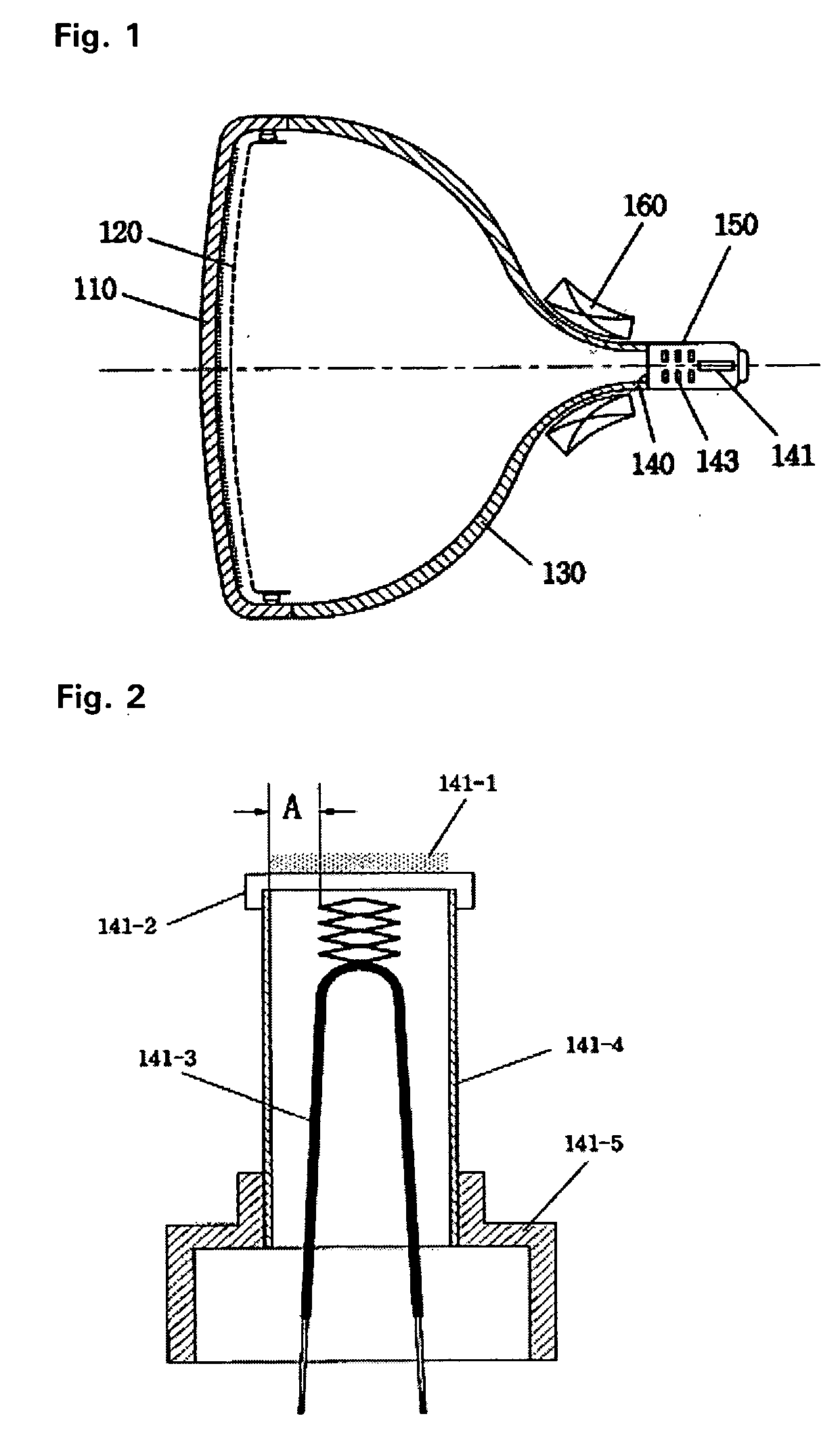
[0001] This Nonprovisional application claims priority under 35 U.S.C. § 119(a) on Patent Application No. 10-2003-0048729 filed in Korea on Jul. 16, 2003, the entire contents of which are hereby incorporated by reference. BACKGROUND OF THE INVENTION [0002] 1. Field of the Invention [0003] The present invention relates to a cathode ray tube including an electron gun having a heater and a method for manufacturing the same. Specifically, the present invention relates to a cathode ray tube including an electron gun having a heater for applying heat to an oxide cathode to emit electrons and a method for manufacturing the same. [0004] 2. Description of the Background Art [0005]FIG. 1 illustrates a conventional cathode ray tube. In general, the cathode ray tube includes a panel 110 on which a fluorescent material is coated, a shadow mask 120 combined with the inner side of the panel to select colors, a funnel 130 combined with the panel 110, a neck 150 in which an electron gun 140 is locat...

Claims


Application Information

Patent Timeline
Patent Type & Authority Applications(United States)
IPC IPC(8): H01J1/20H01J29/48H01J1/22H01J9/08H04N9/04
CPCH01J2201/2882H01J1/22H01J29/48
Inventor LEEM, NAM LEEN
Owner LG PHILIPS DISPLAY KOREA CO LTD
Why Eureka
Try Eureka