
Closed-loop purging system for laser

a laser and closed loop technology, applied in lasers, laser details, active medium materials, etc., can solve the problems of increasing the contaminant level, and achieve the effect of reducing the organic vapor content and increasing the probability of reactions

Inactive Publication Date: 2005-01-20
COHERENT INC
View PDF1 Cites 6 Cited by
  • Summary
  • Abstract
  • Description
  • Claims
  • Application Information

AI Technical Summary

Benefits of technology

[0008] The present invention is directed to a method of minimizing contamination of optical components of a laser, the components being located in a gaseous atmosphere within an enclosure. The gaseous atmosphere can contain contaminants including water vapor, organic vapor, and suspended particulate matter. These contaminants may be present at some low level, for example, hundreds of parts per billion or less, immediately after the components are placed in the enclosure. The contaminant level can increase with both operational and non-operational time of the laser.
[0013] Maintaining a low organic vapor content in a laser resonator is particularly important if the laser resonator is an ultrafast laser resonator or a laser resonator arranged to generate ultraviolet laser radiation. The relatively high-energy of ultraviolet laser radiation, multiphoton processes in the case of ultrafast lasers, generating longer wavelength radiation can increase the probability of reactions between the laser radiation and the organic vapors or their condensates. As noted above, products of these reactions, including particulate matter, can lead to unstable operation of the laser, or accelerated damage to optical components of the laser resonator.

Problems solved by technology

The contaminant level can increase with both operational and non-operational time of the laser.

Method used


Image

  • Closed-loop purging system for laser
  • Closed-loop purging system for laser
  • Closed-loop purging system for laser

Examples


Embodiment Construction

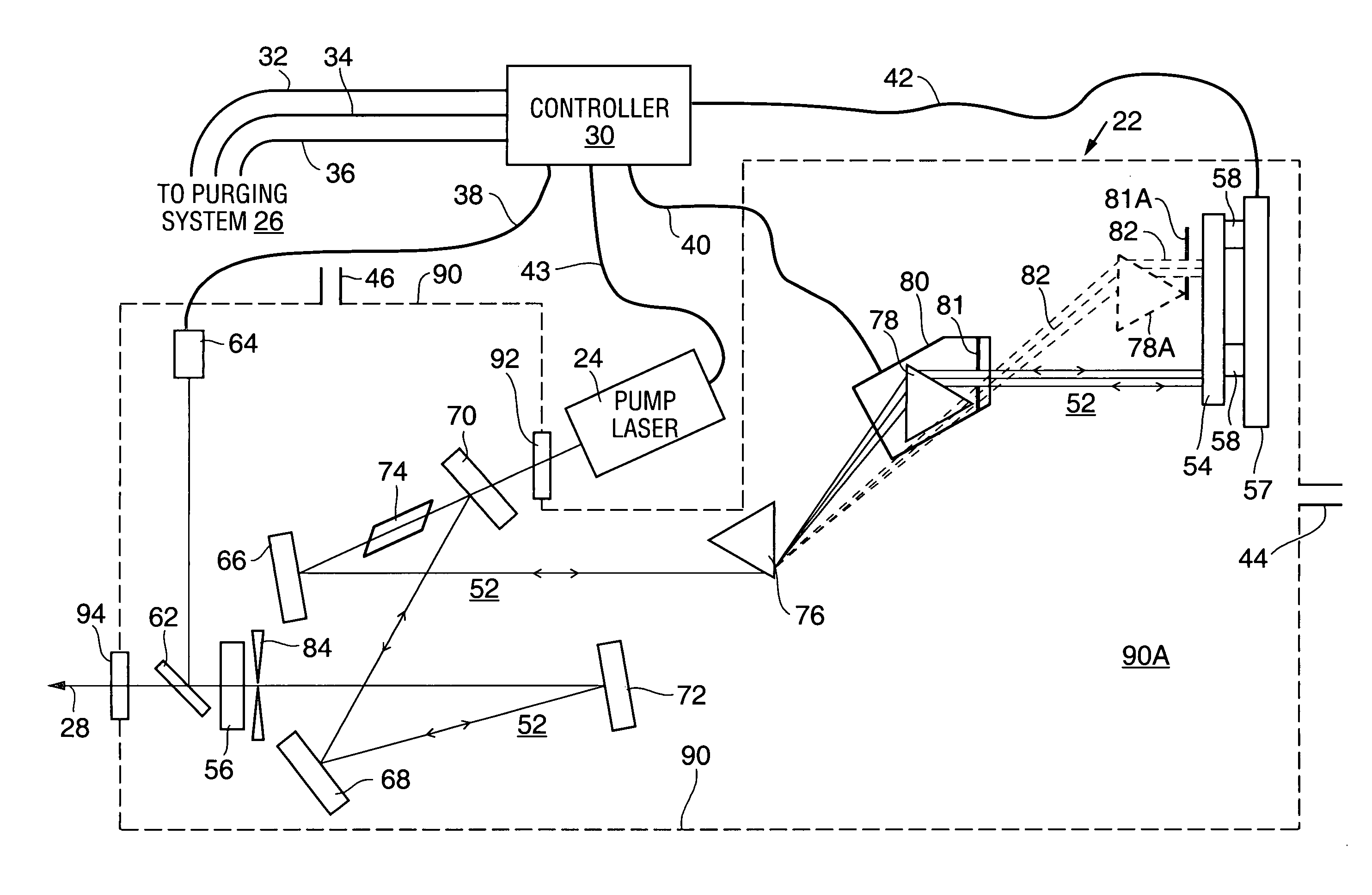
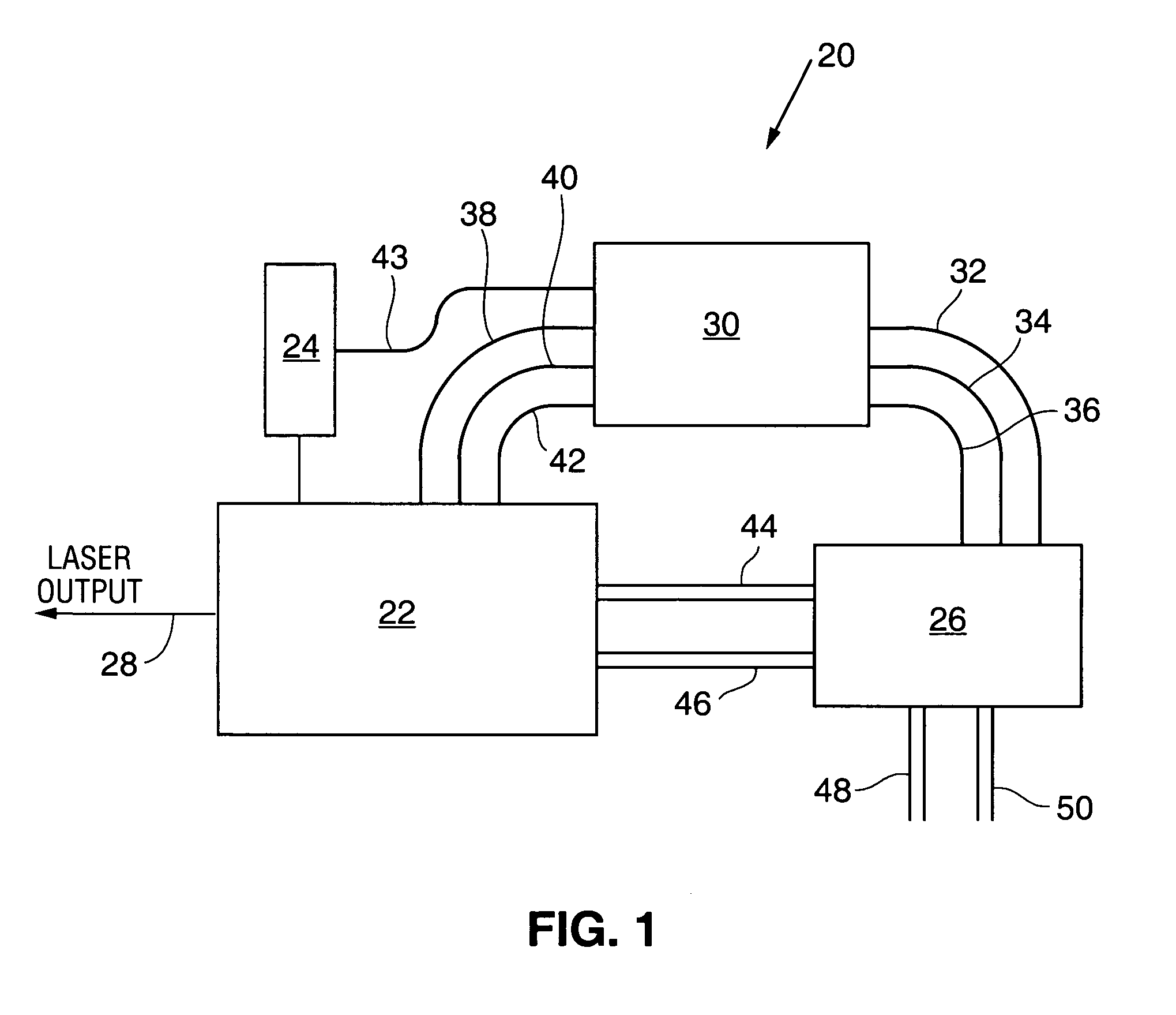
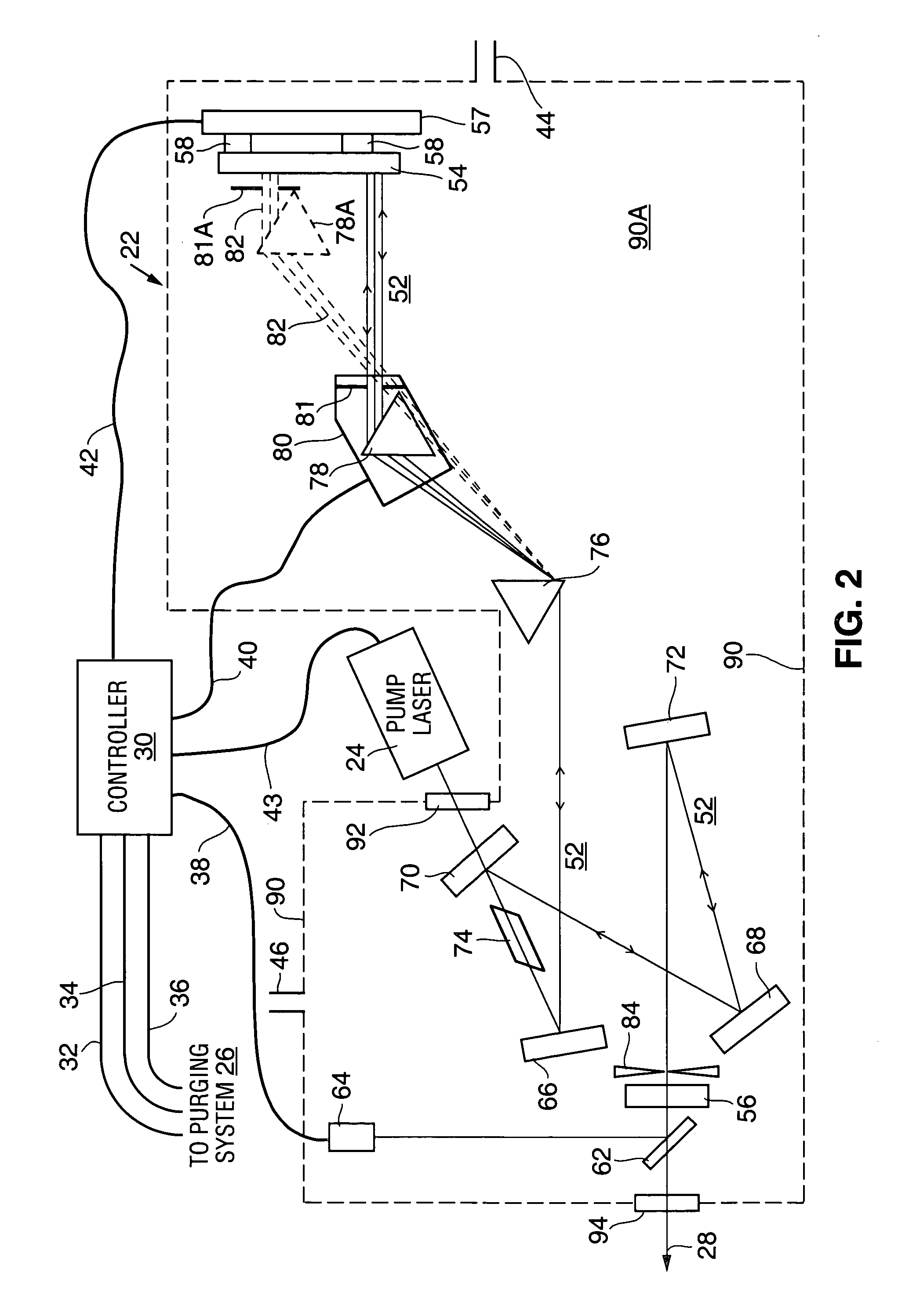
[0018] Referring now to FIG. 1, laser 20 includes a laser resonator 22, a source 24 of optical pump light, and a purging system 26 in accordance with the present invention. In this example, laser resonator 22 is an ultrafast laser resonator delivering laser radiation in the form of ultrafast output pulses 28. Laser 20 also includes a controller 30 arranged to control operations and parameters the laser resonator, the pump light source, and the purging system. Controller 30 controls operations of purging system 26 via electrical connections 32, 34, and 36. The controller controls operations and parameters of laser resonator 22 via electrical connections 38, 40, and 42, and controls pump light source 24 via electrical connection 43. Purging system 26 is cooperative with laser resonator 22 via conduits 44 and 46. Purging system 26 also includes conduits 48 and 50, which connect with a desiccant module (not shown in FIG. 1) in the purging system. The function of conduits 48 and 50 is de...


PUM


Abstract

A method of minimizing contamination of optical components of a laser resonator is disclosed. The resonator components are located in an enclosure, which may contain contaminants including water vapor and organic favor released by the optical components, mounts of the optical components, or the enclosure itself. The enclosure may also contain suspended particulate matter. In order to reduce the level of these contaminants, a purging system extracts gas from the enclosure and passes the gas through a desiccant, an organic vapor trapping material, and a particulate matter filter then returns the extracted gas to the enclosure. The purging system is particularly useful for ultrafast lasers and ultraviolet lasers where the power of the laser radiation increases the probability of destabilizing reactions between laser radiation and contaminants.

Description

CLAIM OF PRIORITY [0001] This application is a continuation of U.S. patent application Ser. No. 09 / 901,857, filed Nov. 25, 2002, entitled “CLOSED-LOOP PURGING SYSTEM FOR LASER,” which is hereby incorporated herein by reference.TECHNICAL FIELD OF THE INVENTION [0002] The present invention relates generally hermetic sealing of lasers. The invention relates in particular to a closed-loop purging system for water vapor, organic vapor and particulate content in an enclosure surrounding an ultrafast laser resonator or an ultraviolet (UV) laser resonator. BACKGROUND [0003] Ultrafast lasers are generally regarded as being lasers that deliver output radiation in pulses having a duration of a few hundred femtoseconds or less. One common ultrafast laser is a Ti:sapphire laser, which can be arranged to deliver output radiation at wavelengths between about 700 nanometers (nm) and about 1000 nm. The pulses delivered often have a relatively low energy, for example, tens of millijoules (mJ) to as l...

Claims


Application Information

Patent Timeline
Patent Type & Authority Applications(United States)
IPC IPC(8): H01S3/02
CPCH01S3/027H01S3/1625H01S3/1112H01S3/094038
Inventor PANG, YANGPHILPOTT, MATTHEW PERRY
Owner COHERENT INC
Learn More