Method for evaluating changes in resistance of electric resistance member and image forming apparatus using same

a technology of resistance value and resistance value, which is applied in the direction of resistance/resistance/impedence, electrographic process apparatus, instruments, etc., can solve the problems of insufficient electric charge supplied to the transfer belt, decrease in the resistance value insufficient resistance of the resistivity of the transfer belt, etc., to achieve good image quality and without transfer defects

Inactive Publication Date: 2005-01-20
RICOH KK
View PDF59 Cites 51 Cited by
  • Summary
  • Abstract
  • Description
  • Claims
  • Application Information

AI Technical Summary

Benefits of technology

[0011] The present invention was created in view of the above-described difficulties. It is an object of the present invention to provide an image forming apparatus equipped with an electric resistance member which can maintain good image quality, without transfer defects such as insufficient transfer, even in a long-term use, based on utilization of a simple measurement method.

Problems solved by technology

However, the following problems were associated with the transfer belts.
Furthermore, the transfer belt was degraded, for example, by an electric discharge between an image carrier and a transfer roller, which resulted in the formation of a conductive path on the transfer belt and decreased the resistance value of the transfer belt.
Thus, because the resistance value of the transfer belt changes with time, the resistivity thereof will change if such a belt is used for a long time.
As a result, the quantity of electric charge supplied to the transfer belt could be insufficient and the image density could decrease due to such an insufficient transfer or, conversely, the quantity of electric charge supplied to the transfer belt could be too high, causing partial discharge and transfer loss which corresponds to the discharge.
For this reason, a long time was required to determine the changes in the resistance value of one belt with time.
As a result, a problem associated with power sources for supplying a bias to bias application means in each transfer location rises, for example, in case of tandem color image forming apparatuses with four transfer locations.
The problem is that even if the leaking current is detected from transfer locations of the transfer belt, it is unclear from which location the current has leaked.
As a result, it was not clear which power source output has to be controlled and how it should be done, and the differential constant current control or constant voltage control based on current value correction could not be used.
Problems associated with the transfer belt as a transfer member were described above, but problems caused by changes in the resistance value with time are also associated with electric resistance members.
In particular, the problems are especially easily caused by changes in the resistance value of a photosensitive body, which is a change carrying member of the image forming apparatus, or a development roller.

Method used


Image

  • Method for evaluating changes in resistance of electric resistance member and image forming apparatus using same
  • Method for evaluating changes in resistance of electric resistance member and image forming apparatus using same
  • Method for evaluating changes in resistance of electric resistance member and image forming apparatus using same

Examples


example 1

[0059] The relationship between the fluctuation characteristic of the surface resistivity in the continuous voltage application interval and the effect produced on the image in continuous copying and timed copying was studied.

[0060] First, intermediate transfer belts of seven types were fabricated and changes in the surface resistivity within a 2-100 seconds interval were studied by using the above-described method for measuring the surface resistivity. The results are shown in FIG. 5.

[0061] The intermediate transfer belts of seven types that were used for the test were fabricated by the following method. Belts Nos. 1-4, 6, 7 were monolayer endless belts composed of a polyimide resin. More specifically, they were fabricated by the following method. Carbon black was dispersed in a solution of a polyamic acid, the dispersion was poured into a cylindrical mold and heated to a temperature of 100-150° C., while rotating the cylindrical mold. As a result, the solvent was evaporated and ...

example 2

[0071] The control by the same voltage value and the control by the same current value were studied on the belts Nos. 1, 2, 4, 7 with a small absolute value Δρs of the amount of changes in the surface resistivity, which showed good results in the above-described tests. The voltage value and current value for the transfer bias were determined from the transfer ability observed when a belt with a standard surface resistance of 11 [Log(Ω / )] was used. As a result, when the belts Nos. 1, 2, 4, and 7 were constant voltage controlled by the same voltage value, the belts Nos. 1 and 7 were found to demonstrate insufficient or excessive transfer. On the other hand, when the belts Nos. 1, 2, 4, and 7 were constant current controlled by the same current value, good images were obtained for the belts Nos. 1, 2, 4, and 7.

[0072] The above-described results demonstrated that the constant current control allows for a wider tolerance with respect to resistance fluctuations than the constant voltage ...

example 3

[0073] Changes in the images caused by the position of transfer roller were studied by varying the position of the transfer roller.

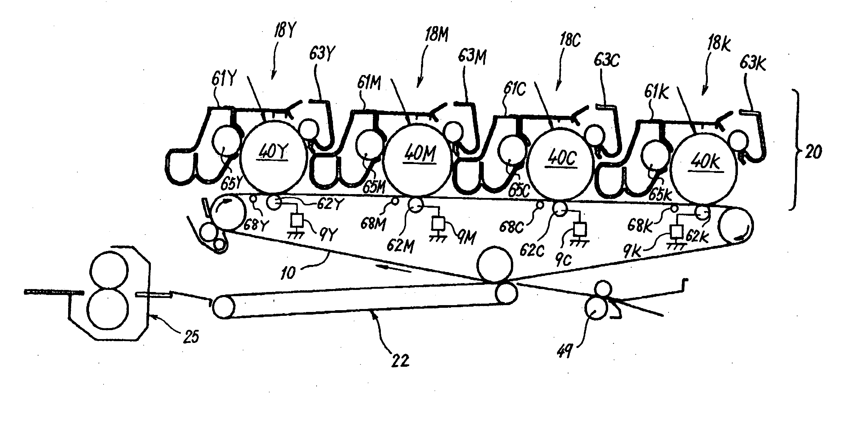
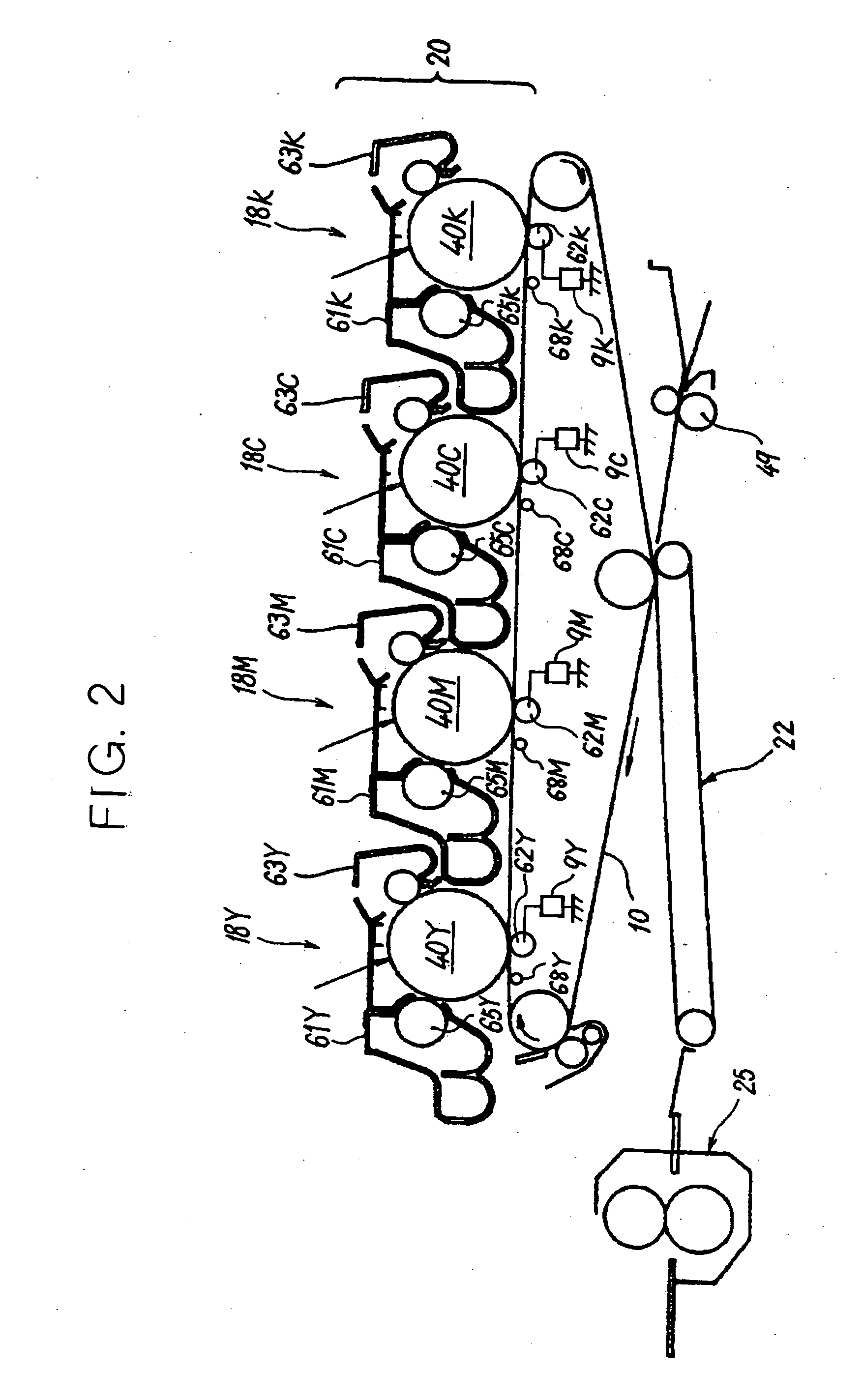
[0074] First, the belts used in Example 1 were installed as the intermediate transfer belt 10 in the image forming apparatus in which the transfer roller 62 was provided in the position shown in FIG. 6, and one copy was made under the constant current control.

[0075] As a result, a transfer non-uniformity caused by abnormal charge was confirmed for all the belts other than the belt No. 2. In this case, the transfer roller 62 was far from the transfer nip portion, as follows from FIG. 6. This is apparently why an electric field in the gap close to the nip exit increased, causing an abnormal discharge in this region. Furthermore, in the belts other than the belt No. 2, the surface resistivity assumed a high value of 10 [Log(Ω / )] and the electric current could not flow easily in the circumferential direction of the belt. As a result, the applied voltage in...


PUM


Abstract

A method for evaluating an electric resistance member of an image forming apparatus which can maintain good image quality, without the occurrence of transfer defects such as insufficient transfer, even in a long-term use. An intermediate transfer belt of the image forming apparatus, which is evaluated based on a fluctuation characteristic of the resistivity in a period of continuous voltage application, is used. The absolute value Δρs of the amount of changes in the surface resistivity of the intermediate transfer belt within 2 seconds to 100 seconds from the beginning of voltage application is 0.3 [Log(Ω / )] or less, when the surface resistivity ρs is measured by applying a voltage of 500 V. The absolute value Δρv of the amount of changes in the volume resistivity within 2 seconds to 100 seconds from the beginning of voltage application is 0.5 [Log(Ω·cm)] or less, when the volume resistivity ρv is measured by applying a voltage of 200 V.

Description

BACKGROUND OF THE INVENTION [0001] 1. Field of the Invention [0002] The present invention relates to a method for evaluating changes in the resistance of an electric resistance member, and more particularly to a method for evaluating the electric charge carrying member of an image forming apparatus. [0003] 2. Description of the Related Art [0004] Image forming apparatuses such as copiers, facsimile devices, and printers are provided with an image carrier, a latent image carrier, and a developing agent carrier as members that are electrified and carry an electric charge. Specific examples of such carriers include a photosensitive body, a developing roller, and a transfer member. In case of image forming apparatuses comprising multiple toners, such as color imaging apparatuses, a transfer belt is used as the transfer member. [0005] Tandem color image forming apparatuses are known as the image forming apparatuses having a transfer belt. The tandem color image forming apparatuses are pr...

Claims


Application Information

Patent Timeline
Patent Type & Authority Applications(United States)
IPC IPC(8): G03G15/01G01R27/02G03G15/16
CPCG03G15/1685
Inventor SAWAI, YUUJIFUJIWARA, YOSHIHIROKAYAHARA, SHINOGIYAMA, HIROMITAKEHARA, ATSUSHIYOSHIDA, KENKATO, SHINJI
Owner RICOH KK
Why Eureka
Try Eureka