Axial stability in rock bits

a technology of axial stability and rock bits, applied in the field of axial stability in rock bits, can solve the problems of affecting the performance of the bit, so as to achieve the effect of evaluating the bit performan

Inactive Publication Date: 2005-01-20
SMITH INT INC
View PDF5 Cites 45 Cited by
  • Summary
  • Abstract
  • Description
  • Claims
  • Application Information

AI Technical Summary

Benefits of technology

[0008] In general, one aspect of the invention relates to a method for designing a bit for boring in earth formations. The method includes defining parameters for a calculation, wherein the parameters relate to a geometry of the bit, calculating to determine interference between the bit and the earth formations, obtaining vertical displacements with respect to a bit revolution based on the interference between the bit and the earth formations, and applying a criterion to the vertical displacements to evaluate bit performance.

Problems solved by technology

Significant expense is involved in the design and manufacture of drill bits.
However, roller cone bits are more complex than fixed cutter bits in that cutting surfaces of the bit are disposed on the roller cones, wherein each roller cone independently rotates relative to the rotation of the bit body about axes oblique to the axis of the bit body.
Some bit bounce is to be expected during a drilling operation, however, substantial fluctuations in vertical movements result in axial instability.
Thus, bit bounce is typically undesirable, because it results in vibrations in the drill string causing inefficiency in the drilling operation and, in some cases, potentially damaging the bit prematurely.
Until recently, no reliable roller cone bit models had been developed which could take into consideration the location, orientation, size, height, and shape of each cutting element on the roller cone, and the interaction of each individual cutting element on the cones with earth formations during drilling.
Any axial instability during drilling will have a negative impact on the bit and the drill string.
In addition, axial instability also reduces drilling efficiency.

Method used


Image

  • Axial stability in rock bits
  • Axial stability in rock bits
  • Axial stability in rock bits

Examples


Embodiment Construction

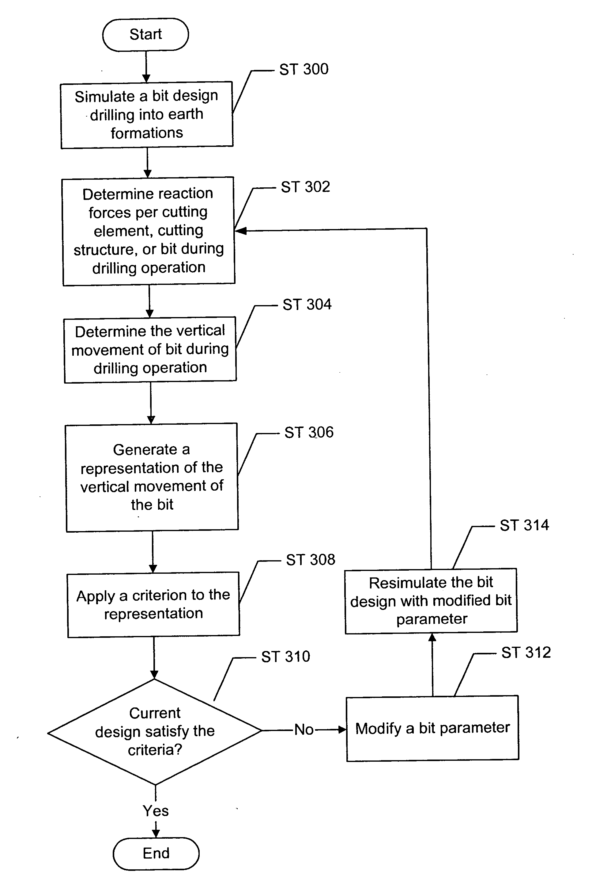
[0028] The present invention involves analyzing axial stability through simulation to evaluate cutting structure performance, e.g., ROP, footage drilled, etc. In general, the present invention involves defining a set of parameters of a cutting structure during a drilling operation in a simulation and executing the simulation in view of the defined parameters. The present invention further involves obtaining vertical movements with respect to revolution of the cutting structure and applying a criterion to the vertical movements to evaluate the cutting structure performance.

[0029] In one or more embodiments, the present invention may generally be characterized as comprising three phases: simulation, analysis, and optimization. In the first phase, simulation includes defining a design of a bit for drilling into the earth formations and representing the bit during a drilling operation. One example of a method for simulating a bit drilling through earth formations can be found in U.S. P...


PUM


Abstract

A method for designing a bit for boring earth formations includes defining parameters for a calculation, where the parameters relate to a geometry of the bit, calculating to determine interference between the bit and the earth formations, obtaining vertical displacements with respect to a bit revolution based on the interference between the bit and the earth formations and applying a criterion to the vertical displacements to evaluate bit performance.

Description

CROSS-REFERENCE TO RELATED APPLICATIONS [0001] This is an utility application, which claims priority pursuant to 35 U.S.C. §119(c) to U.S. Provisional Application No. 60 / 487,495, filed on Jul. 15, 2003. That application is expressly incorporated by reference it its entirety.BACKGROUND OF INVENTION [0002] Roller cone rock bits and fixed cutter bits are commonly used in the oil and gas industry for drilling wells. FIG. 1 shows one example of a conventional drilling system drilling an earth formation. The drilling system includes a drilling rig (10) used to turn a drill string (12), which extends downward into a well bore (14). Connected to the end of the drill string (12) is roller cone-type drill bit (20) via a bottom hole assembly (16). A roller cone-type drill bit is shown in further detail in FIG. 2. Roller cone bits (20) typically comprise a bit body (22) having an externally threaded connection at one end (24), and a plurality of roller cones (26) (usually three as shown) attach...

Claims


Application Information

Patent Timeline
Patent Type & Authority Applications(United States)
IPC IPC(8): E21B10/08
CPCE21B10/08
Inventor CENTALA, PRABHAKARANBOUDRARE, MOHAMEDHUANG, SUJIAN
Owner SMITH INT INC
Why Eureka
Try Eureka