Vehicle transmission

a transmission and vehicle technology, applied in fluid gearings, transportation and packaging, gearings, etc., can solve the problems of reducing the durability of universal joints, noise and vibration, and complicated repair or maintenance, and achieve the effect of optimal balance and easy disassembly

Inactive Publication Date: 2005-01-27
KANZAKI KOKYUKOKI MFG
View PDF8 Cites 47 Cited by
  • Summary
  • Abstract
  • Description
  • Claims
  • Application Information

AI Technical Summary

Benefits of technology

[0013] An object of the present invention is to provide a vehicle transmission for a working vehicle such as a riding lawn mower, wherein a pair of transmission devices, such as HSTs, for driving respective axle

Problems solved by technology

If the HST (for example, its oil duct plate) must undergo repair or maintenance, the deceleration gear casing must be removed from the HST casing incorporating the troubled HST, thereby complicating its repair or maintenance.
Another problem of the transmission is that the universal joint coupling is extended between the (rear) end of the center casing and the engine in the fore-and-aft direction.
If the heights of the horizontal output shaft of the engine and the horizontal input shaft of the transmission are considerably different from each other and the distance therebetween in the fore-and-aft direction is restricted, the universal joint coupling must be considerably vertically angled (steep) to be interposed between the shafts so as to disturb the efficiency of power transmission, to cause noise and vibration, and to reduce the durability of

Method used


Image

  • Vehicle transmission
  • Vehicle transmission
  • Vehicle transmission

Examples


first embodiment

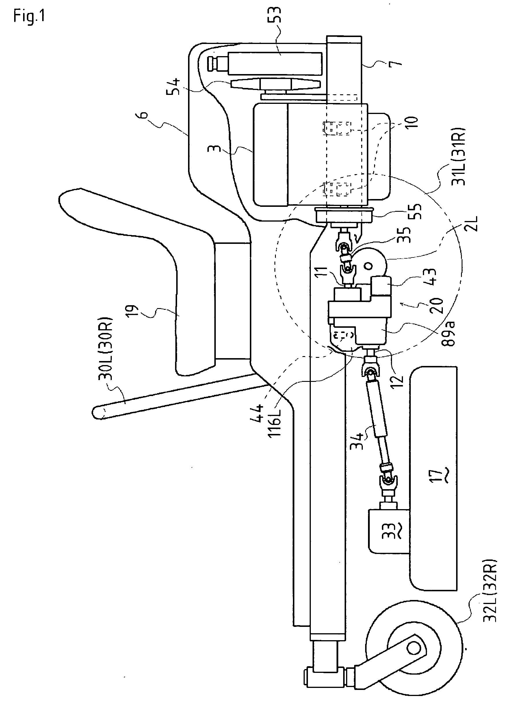
[0089] A general configuration of a riding lawn mower shown in FIG. 1, equipped with a transmission 20 according to the invention, will be described. A vehicle frame 7 is extended between the front and rear ends of the riding lawn mower. Left and right front casters 32L and 32R are supported at the front end of vehicle frame 7. The riding lawn mower is provided at its lateral middle portion with a mower unit 17 vertically movably suspended below vehicle frame 7 behind casters 32L and 32R. An input gearbox 33 is mounted on the top of mower unit 17. Transmission 20 having a forwardly projecting PTO shaft 12 is disposed behind mower unit 17 so as to transmit power from PTO shaft 12 to gearbox 33 via a universal joint coupling 34, thereby a rotary blade in mower unit 17.

[0090] A horizontal crankshaft engine 3 is disposed behind transmission 20 and is elastically supported by frame 7 via vibro-isolating rubbers 10. Engine 3 is provided with a radiator fan 54 and a radiator 53 therebehind...

second embodiment

[0114]FIG. 9 illustrates a riding lawn mower equipped with a transmission 120 according to a The riding lawn mower is the same as that of FIG. 1 except for transmission 120. A configuration of transmission 120 will now be described with reference to FIGS. 9 to 13.

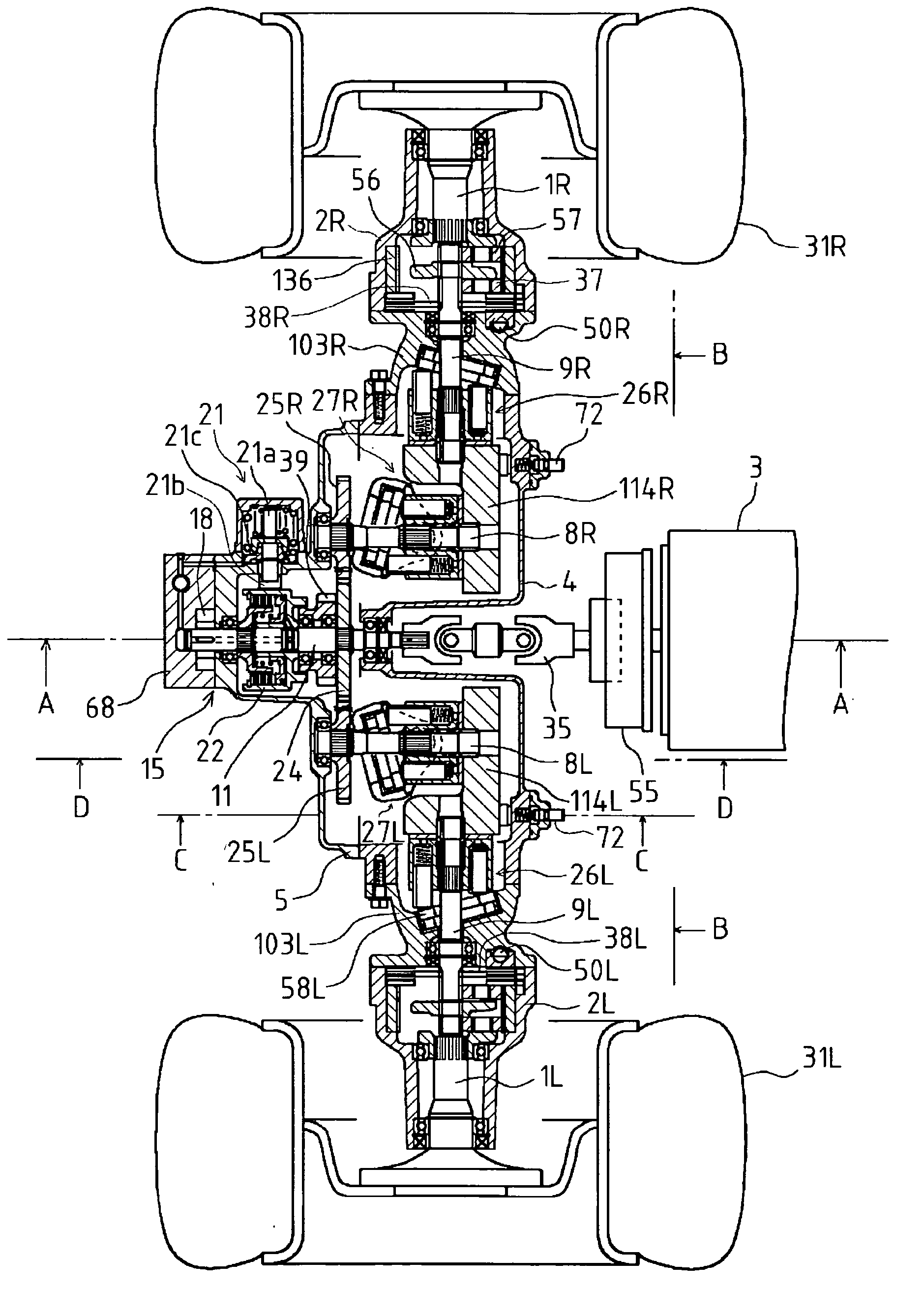
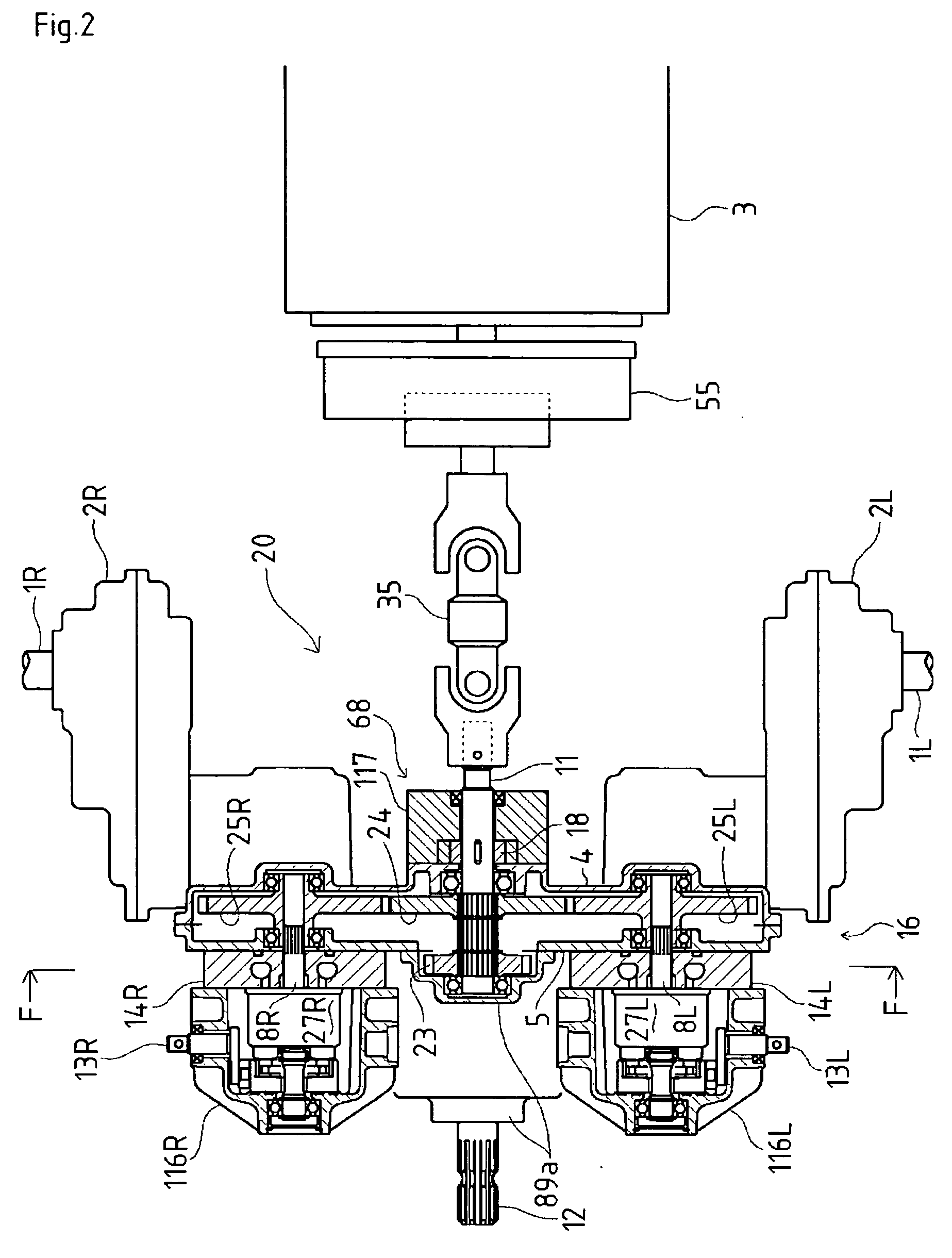
[0115] Transmission 120 of the present embodiment is provided with center casing 16 constituted by front and rear casing parts 5 and 4 joined to each other through a vertical lateral joint surface. Center casing 16 of transmission 120 serves as center casing 16 of transmission 20 reshaped to be integrated with the upper pump housing portions of HST casings 116L and 116R. Left and right motor casings 103L and 103R are mounted onto left and right side ends of center casing 16 so as to be extended oppositely laterally outward from center casing 16. Deceleration gear casings 2L and 2R of transmission 120 are mounted onto outer sides of respective motor casings 103L and 103R so as to extend oppositely laterally outward from mot...

third embodiment

[0124] As shown in FIG. 10, the PTO clutch housing portion of front casing part 5 is expanded laterally on one of left and right sides of PTO clutch 15 so as to form a chamber in which PTO brake 21 is disposed. PTO brake 21 of transmission 120 comprises a thrust pin 21a disposed perpendicularly to input shaft 11 and biased toward PTO clutch casing 22 by springs. A soft pad 21b is provided on its tip with thrust pin 21a toward clutch casing 22. Thrust pin 21a is fixedly provided thereon with a brake piston 21c so as to be hydraulically biased against the spring by oil supplied into the chamber from charge pump 68. The same PTO brake 21 of a transmission 220 will be detailed in the later-description of transmission 220.

[0125] When input shaft 11 is rotated, charge pump 68 supplies oil to both the chamber in clutch casing 22 and the chamber of PTO brake 21 so as to engage PTO clutch 15 and hold thrust pin 21a apart from clutch casing 22. If input shaft 11 is stopped or almost stationa...


PUM


Abstract

A vehicle transmission having a pair of left and right HSTs for driving respective axles is applicable for a riding lawn mower. The transmission comprises a center casing incorporating a distributing drive train. In the fore-and-aft direction, an input shaft of the distributing drive train projects from the center casing toward a prime mover, and a PTO shaft for driving a mower unit projects from the center casing opposite to the prime mover. A pair of left and right deceleration drive train casings for incorporating respective deceleration gear trains and supporting the respective axles are disposed on respective left and right sides of the center casing. A pair of left and right stepless transmission mechanisms, each of which is drivingly interposed between the distributing drive train and each of the deceleration gear trains in the deceleration gear train casings, are mounted on left and right side portions of the center casing opposite to the prime mover in the fore-and-aft direction.

Description

BACKGROUND OF THE INVENTION [0001] 1. Field of the Invention [0002] The present invention relates generally to a transmission of a vehicle, such as a riding mower and more specifically relates to a transmission distributing power between left and right stepless transmission mechanisms for respective left and right drive axles. [0003] 2. Related Art [0004] As disclosed in Japanese Laid-Open Gazette No. 2000-71790, there is a well-known conventional vehicle transmission for a working vehicle such as a riding lawn mower, which has a pair of HSTs for driving respective drive axles and a PTO shaft for driving a working machine attached to the vehicle. The transmission is provided with a pair of left and right HSTs for respective left and right drive axles, a center casing disposed between HSTs, and a pair of left and right deceleration gear casings supporting the respective left and right drive axles and incorporating the respective deceleration gear trains. [0005] An input shaft project...

Claims


Application Information

Patent Timeline
IPC IPC(8): B60K17/10B60K17/28B62D11/06F16H39/14
CPCB60K17/105B60K17/28Y10T74/18256B62D11/06F16H39/14B60Y2200/223
Inventor ISHII, NORIHIROOHASHI, RYOTA
Owner KANZAKI KOKYUKOKI MFG
Why Eureka
Try Eureka