Valve guide for rocker arm assembly

a rocker arm and valve guide technology, which is applied in the direction of engine components, mechanical equipment, machines/engines, etc., can solve the problems of increasing the overall manufacturing cost of the rocker arm assembly, complicated valve provision, and reducing the assembly time and cost of the rocker arm. , to achieve the effect of reducing the assembly time and cos

Active Publication Date: 2005-01-27
EATON INTELLIGENT POWER LIMITED
View PDF4 Cites 45 Cited by
  • Summary
  • Abstract
  • Description
  • Claims
  • Application Information

AI Technical Summary

Benefits of technology

[0009] It is another object of the present invention to provide an improved rocker arm assembly which achieves the above-...

Problems solved by technology

The need to maintain non-sliding engagement between the end surface of the valve stem tip portion and the rocker arm pad portion, through a relatively greater range of pivoting motion of the rocker arm (in the case of valve deactivation), somewhat complicates the provision of an appropriate valve tip pad por...

Method used


Image

  • Valve guide for rocker arm assembly
  • Valve guide for rocker arm assembly
  • Valve guide for rocker arm assembly

Examples


Embodiment Construction

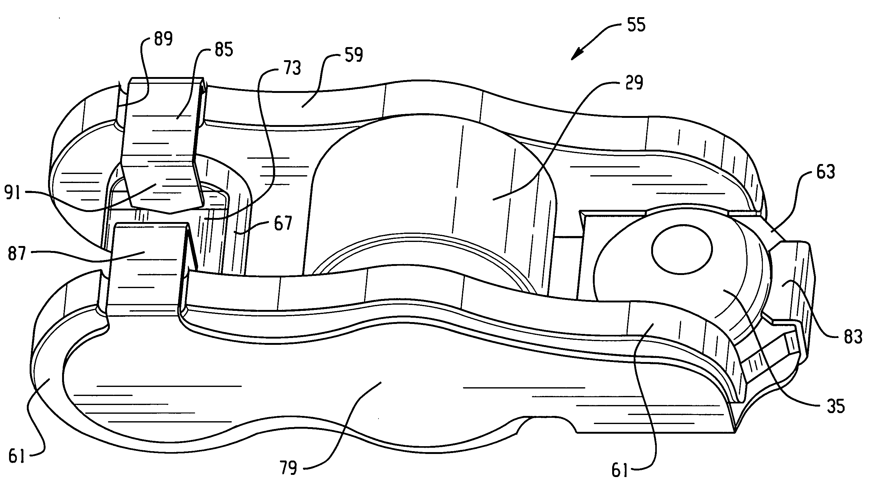
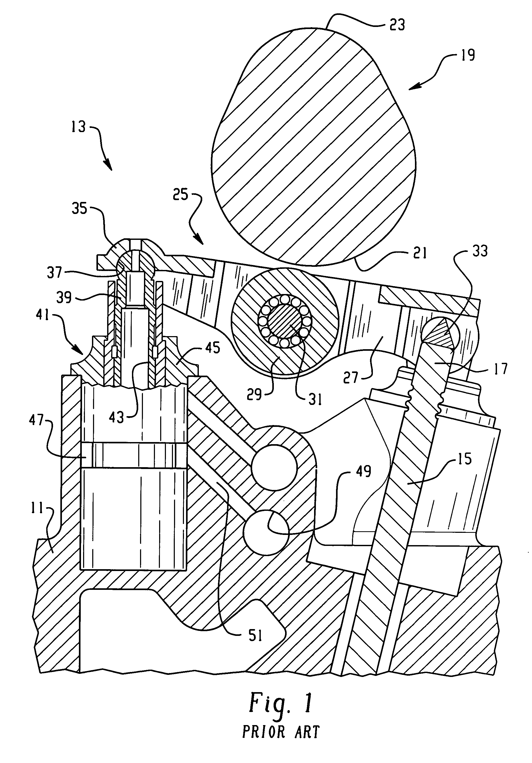
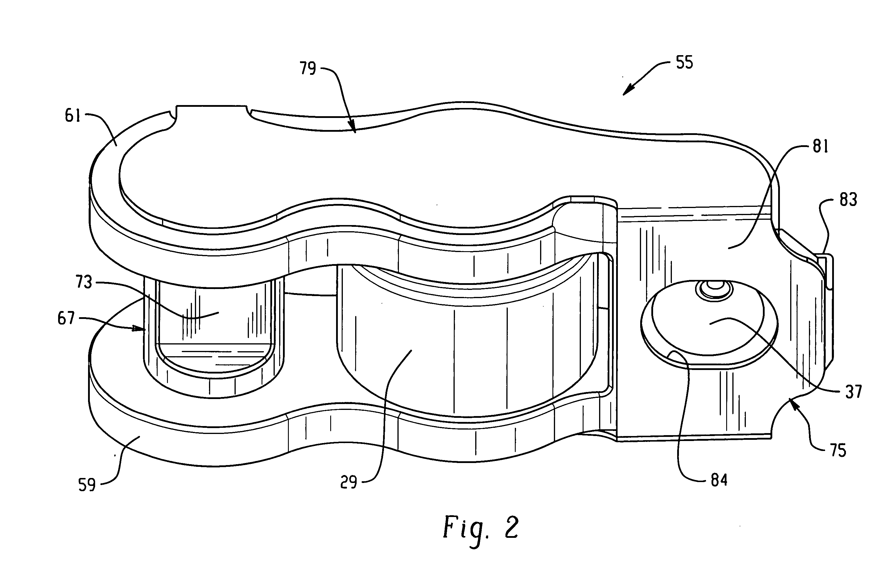
[0019] Referring now to the drawings, which are not intended to limit the invention, FIG. 1 illustrates a portion of a cylinder head 11 of an internal combustion engine of the overhead cam (OHC) type, with which the rocker arm assembly of the present invention may be utilized. In FIG. 1, there is a conventional (“Prior Art”) valve control system, generally designated 13, which is utilized to control the movement (“lift”) of an engine poppet valve 15. The engine poppet valve 15 includes a tip portion 17 (also referred to herein as a “stem tip portion”). As is well known to those skilled in the art, the tip portion 17 is typically surrounded by a spring retainer (not show herein) which serves as the seat for the upper end of a valve return spring (also not shown herein for simplicity).

[0020] The valve control system 13 operates in conjunction with a camshaft, generally designated 19, to provide cyclical opening motion to the engine poppet valve 15, in opposition to the biasing (closi...


PUM


Abstract

A rocker arm assembly (55) for a valve control system in an internal combustion engine including a cylinder head (11), and a poppet valve (15). The valve control system comprises an HLA (41) having a ball plunger portion (39). The assembly (55) comprises a rocker arm (57) including axially spaced apart side walls (59,61) and a portion (63) for engagement with the ball plunger (39). The rocker arm assembly (55) further comprises a cam follower (29) disposed about a mounting shaft (31) extending into shaft openings (65) defined by the side walls (59,61), and a pin member (67) defining a valve pad for engagement with a stem tip portion (17), the pin member extending into pin openings (71) defined by the side walls. The assembly (55) includes a clip member (75) including spaced apart clip side walls (77,79) disposed on the outside of the side walls of the rocker arm (57). A connection portion (81) interconnects the clip side walls to restrain axial movement of the mounting shaft (31) and of the pin member (67). The clip side walls (77,79) include retention portions (85,87) engaging the adjacent side walls (59,61) of the rocker arm and extending therebetween and include terminal portions (91) adjacent the pin member (67) to limit rotation of the pin member about its axis, relative to said rocker arm (57).

Description

BACKGROUND OF THE DISCLOSURE [0001] The present invention relates to valve control systems for internal combustion engines, and more particularly, to an improved rocker arm assembly for use therein. [0002] Valve control systems for engine poppet valves are generally well known in the art. Although not so limited, the present invention is especially adapted for use in valve control systems of the overhead cam (OHC) type, and will be described in connection therewith. In a typical OHC type of valve control system, there is provided, in addition to the engine poppet valve being controlled, a rocker arm assembly, and some sort of “fulcrum” mechanism about which the rocker arm assembly pivots. In addition, an OHC valve control system includes a camshaft defining a cam profile, and the rocker arm assembly includes a cam follower, such as a roller follower member rotatably disposed about, and supported on a shaft, with the shaft being fixed relative to the rocker arm assembly. [0003] Typic...

Claims


Application Information

Patent Timeline
IPC IPC(8): F01L1/18
CPCF01L1/185Y10T74/2107F01L2001/187F01L1/18
Inventor FERRACIN, SERGIOCECUR, MAJO
Owner EATON INTELLIGENT POWER LIMITED
Why Eureka
Try Eureka