
Process control valve

Inactive Publication Date: 2005-01-27
JEROMSON PETER JAMES +1
View PDF7 Cites 65 Cited by
  • Summary
  • Abstract
  • Description
  • Claims
  • Application Information

AI Technical Summary

Benefits of technology

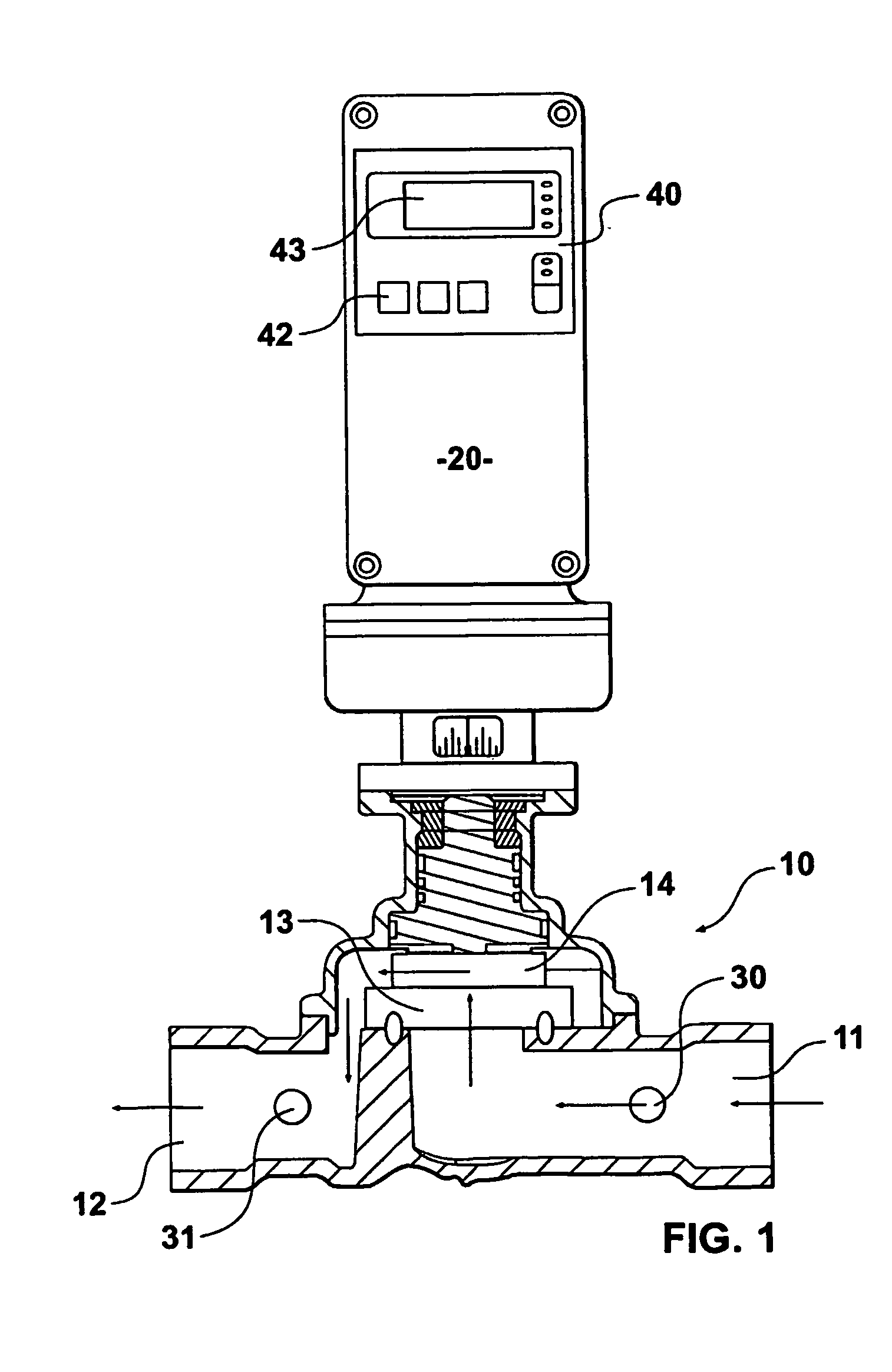
[0018] In another aspect the invention provides a process control valve for installation in a pipeline, the valve having a valve body, the body having at least one fluid inlet port and at least one fluid outlet port; a first disc member capable of defining at least one inlet aperture communicating with said at least one inlet port; and a second disc member capable of defining at least one outlet aperture communicating with said at least one outlet port; the first and second disc members are arranged in sealing contact and are rotatable relative to one another; an electric motor capable of rotating at least one of the discs relative to the other disc; means for determining the relative rotational position of the discs; at least one sensor mounted within the valve body to monitor a desired parameter within the valve body; a microprocessor controller capable of controlling the operation of the motor and hence the relative position of the discs; and wherein the at least one pressure sensor is connected to the microprocessor controller, the at least one inlet aperture is substantially sector shaped and the at least one outlet aperture is substantially sector shaped so that relative rotation of the discs by the electric motor provides control over the desired parameter within the pipeline, and also allows for the fluid flow to be completely impeded when the apertures are not aligned with one another.

Problems solved by technology

Such systems are complex, and require special installation, and in some cases may suffer from a time lag between the sensing of the process perameter, and the action taken to adjust the pressure or flow rate of the fluid.

Method used


Image

  • Process control valve
  • Process control valve
  • Process control valve

Examples


example 2

Pressure Measurement

[0058] If the valve is to measure pressure within the valve body as liquid flows therethrough, the pressure sensor can monitor the dynamic pressure within the valve body, and this information can be converted by appropriate algorithm to the static pressure depending upon various parameters of the valve. Since the pressure sensor will be pre-installed in a specially designed valve body, the characteristics of the valve, and hence the control unit can monitor the static pressure.

example 3

Flow Rate

[0059] If flow rate is to be measured by the control unit and / or the flow rate through the valve determined by adjusting the shear action discs within the valve body then two pressure sensors are preferably used, to monitor the pressure at the input and the output, and the pressure measurements are converted through an appropriate algorithm to a measure of the flow rate. This can be based on Bernoulli's theorem, which defines the relationship between pressure and flow rate within a moving fluid.

example 4

Encoder

[0060] In this example it is preferred that the stepper-motor is connected to a gearbox which is connected to an encoder disc 60, on the suspension shaft, which encoder provides absolute position information to the microprocessor and hence to the stepper-motor. Such an encoder disc 60 is shown in FIG. 7, and has an etched or printed pattern 61 on the disc, enabling an appropriate optical transmitter and receiver to operate in conjunction with the movement of the encoder disc to precisely determine the position of the encoder disc, and hence the position of the moveable valve disc, and in consequence the position of the stepper-motor. The geared stepper-motor itself may be designed to move in increments of 0.024° at the output shaft (after the gearbox) whilst the encoder disc may be designed to any required degree of accuracy, consistent with the cost of the device and the capability of the stepper-motor.

[0061] The encoder disc and its components are shown in FIG. 8 as an ex...


PUM


Abstract

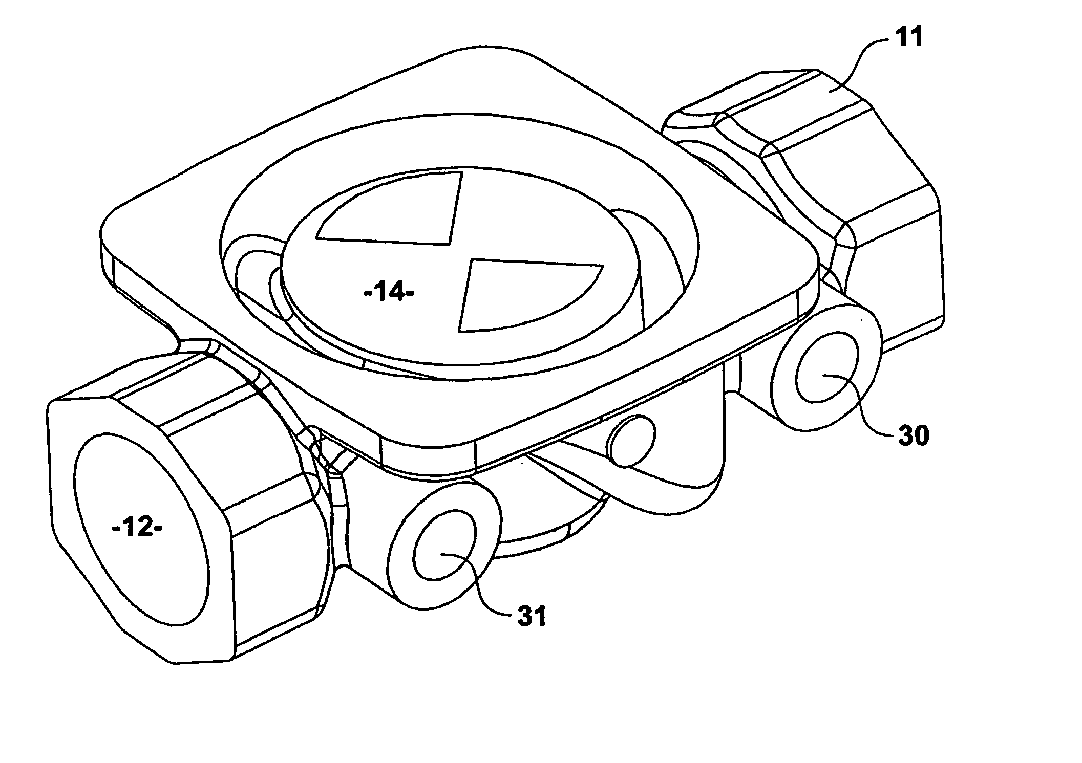
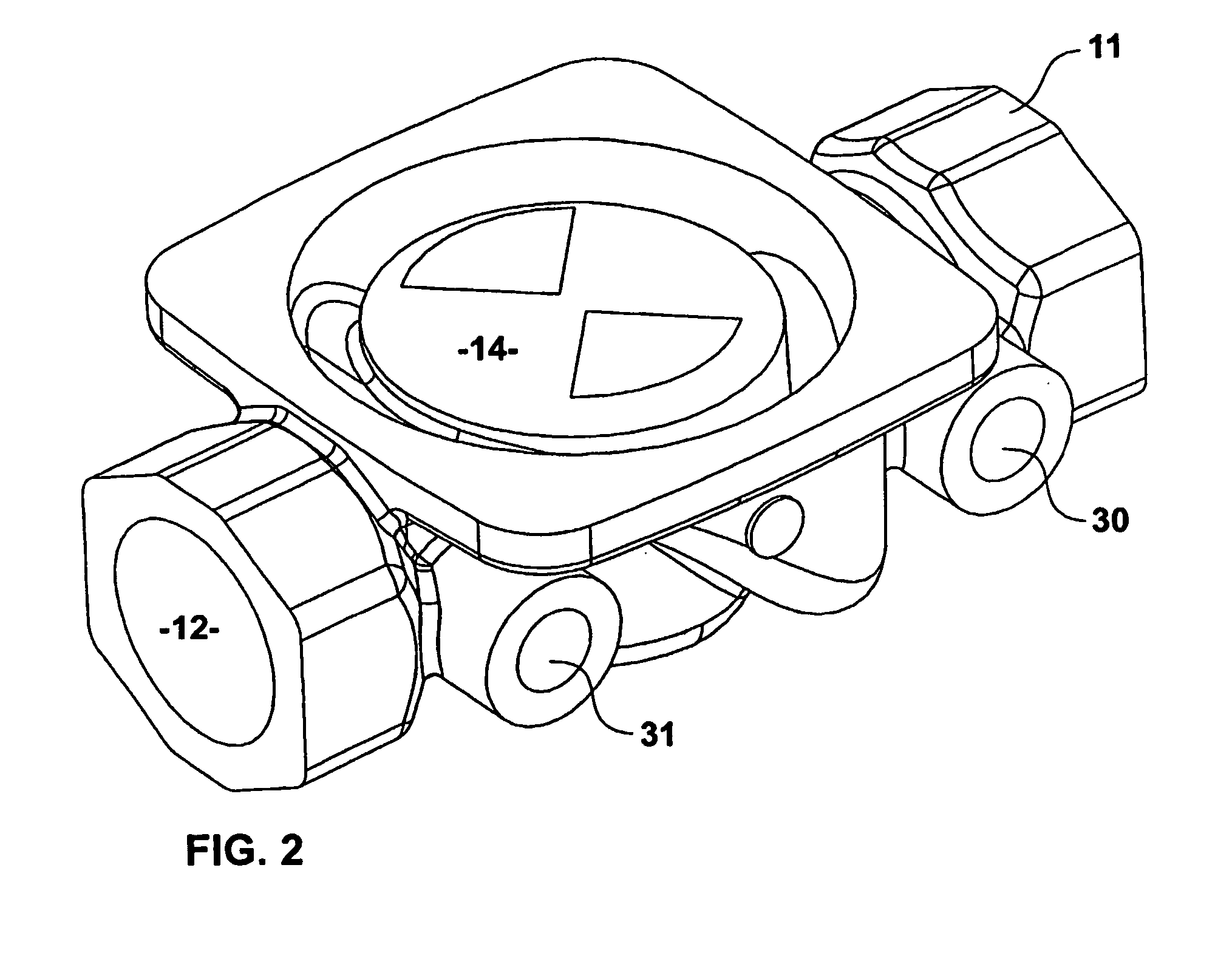
A “plug and playprocess control valve 10 providing closed loop feedback control has a built in microprocessor 40, stepper-motor 20, a position encoder, a valve body having an inlet 11 and an outlet 12, and pressure sensors 30, 31 positioned within the inlet 11 and the outlet 12 of the valve body, the pressure sensors being connected to the microprocessor 20, which is in turn connected to an input from the position encoder, and provided with outputs to the step-per-motor 40. Within the valve body there are a pair of apertured ceramic shear action discs 13, 14. The stepper-motor rotates the upper disc 14 relative to the apertured stator disc 13 to control pressure or flow in the pipeline.

Description

FIELD OF THE INVENTION [0001] This invention relates to process control valves where it is desirable to control the pressure or flow rate of a fluid within a pipeline. BACKGROUND OF THE INVENTION [0002] Traditional flow control valves have made use of globe valves coupled to a pneumatic or hydraulic controller to control the opening or closing of the valve dependent upon measurements made at different positions along the pipeline. Such measurements use, for example, pressure sensors, the output of which is connected to a central controller, which monitors the fluid parameters at a particular section of the pipeline, and sends control signals to the appropriate actuator to adjust the opening or closing of one or more valves. Such systems are complex, and require special installation, and in some cases may suffer from a time lag between the sensing of the process perameter, and the action taken to adjust the pressure or flow rate of the fluid. OBJECT OF THE INVENTION [0003] It is an o...

Claims


Application Information

Patent Timeline
IPC IPC(8): F16K3/08F16K31/04F16K31/08F16K37/00G05D7/06G05D16/20
CPCF16K3/08G05D7/0635F16K31/042F16K37/0091F16K37/0083G05D16/202Y10T137/7761
Inventor JEROMSON, PETER JAMESBILYARD, JAMES RAYMOND
Owner JEROMSON PETER JAMES
Learn More