Water supply system

a water supply system and water supply technology, applied in fluid pressure control, process and machine control, instruments, etc., can solve the problems of increased pressure, increased pressure, and increased pressure, and may be harmful to industrial facilities receiving water from the network

Active Publication Date: 2005-01-27
STREAM CONTROL
View PDF6 Cites 39 Cited by
  • Summary
  • Abstract
  • Description
  • Claims
  • Application Information

AI Technical Summary

Benefits of technology

[0054] It is advantageous that the water supply system be fitted with a bypass gate overriding the DCV such that at the event of malfunction of the system, the bypass opens to thereby provide outlet pressure Pout at an outlet of the PRV corresponding with the nominal output pressure set at the pilot valve.

Problems solved by technology

Excessive pressure may also be harmful for industrial facilities receiving water from the network.
Increasing the pressure at the monitored consumer will necessarily entail a much more significant pressure increase at consumers upstream, even as much as harmful over pressure.
For one thing, over pressure demands more powerful pumping units and is more costly.
Second, it requires a pipe network that can withstand such overpressure.
Then there is a problem of over pressure which can cause damage to the consumers as already mentioned above.
Even more so, non-significant leaks in the pipe network, e.g. minor holes or poor connections of piping elements, become proportionally significant upon pressure increase and may be the reason for some significant loss of fresh water which goes astray.
This may result in one of two undesired extreme positions, the first being complete cut-off of the water supply and the second being providing the consumers with a pressure which is equal to high pressure upstream (as the PRV does not fulfil its function) whereby the water supplier is exposed to malfunctioning liability owing to damages caused to consumers.
Increased openings / closing of the solenoids and valve components may render the system vulnerable to malfunction.
In most cases individual fittings and installations are required which render the installation not cost effective.
The bias chamber is a sensitive element requiring fine adjustments and being susceptible to dirt.
The systems does not offer any bypassing arrangements, whereby malfunctioning of such a system may result in that the consumer will receive excessively high pressure, which may cause damage.

Method used


Image

  • Water supply system
  • Water supply system
  • Water supply system

Examples


Embodiment Construction

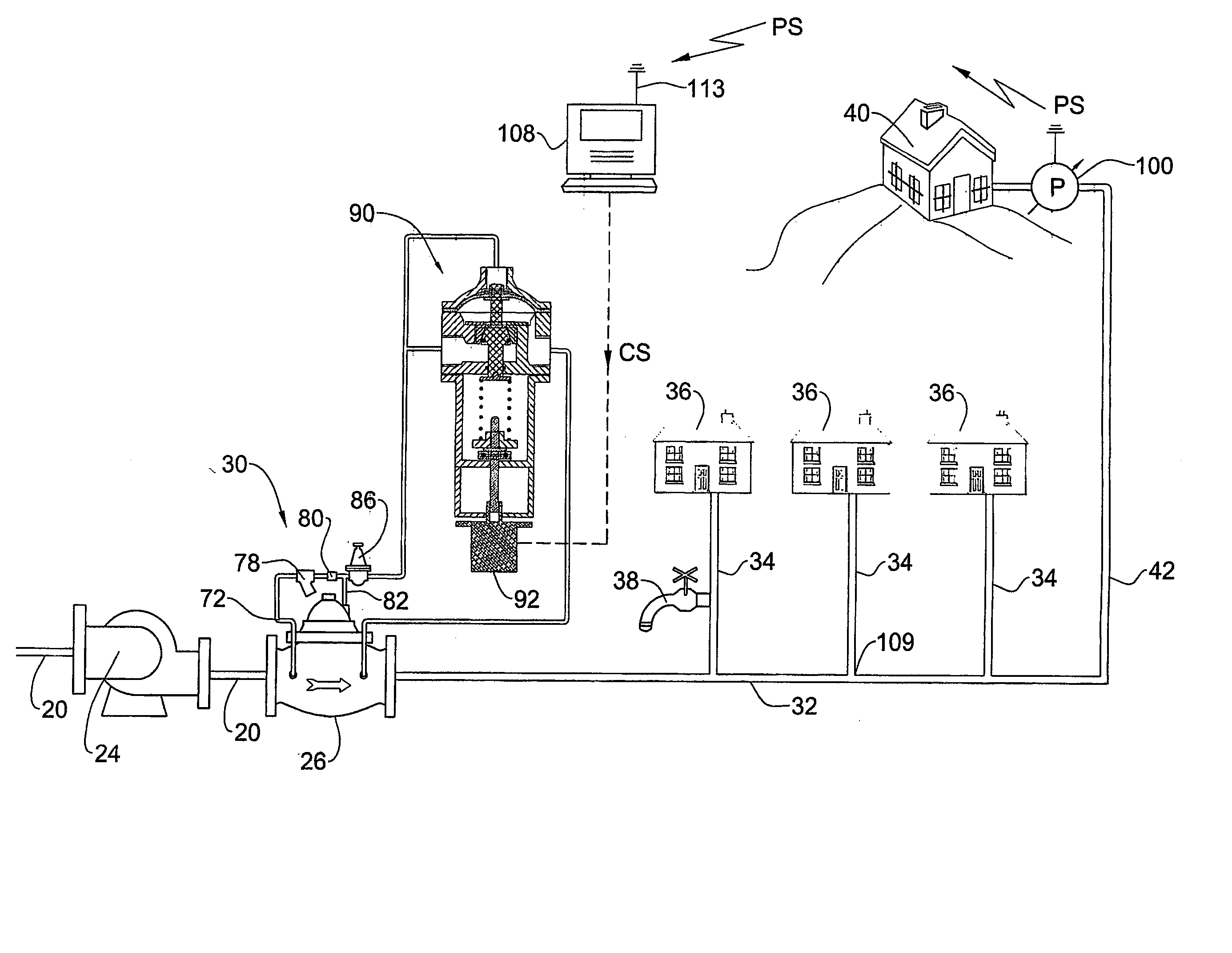
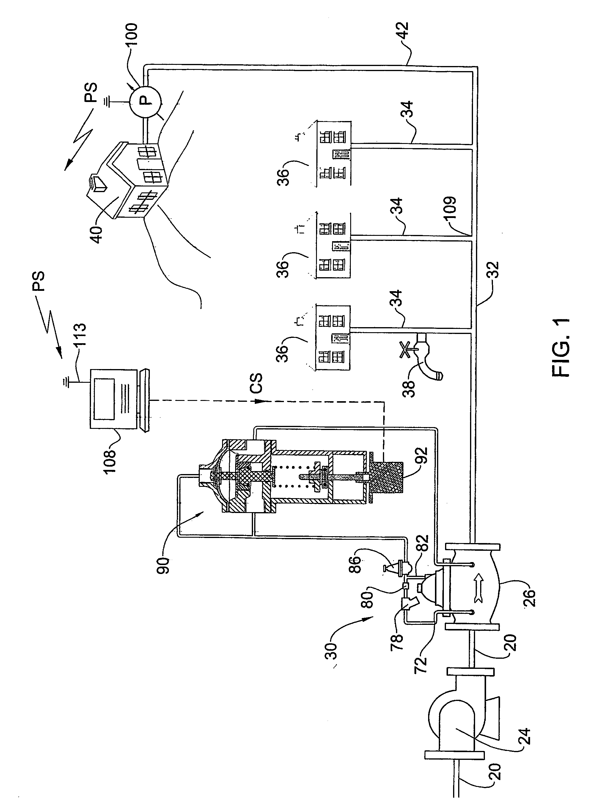
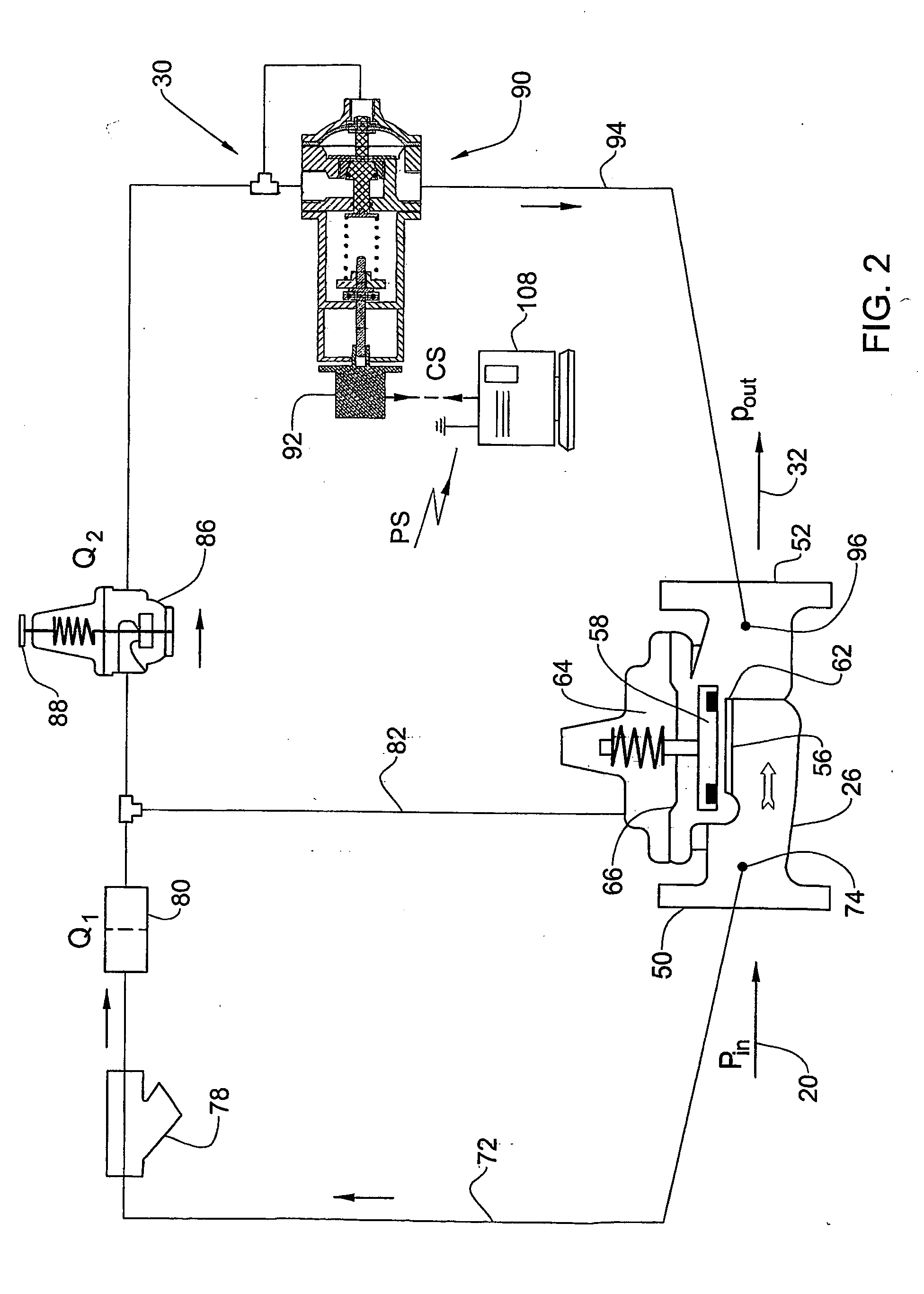
[0073] Attention is first directed to FIG. 1 of the drawings, illustrating by way of a schematic representation, a water supply system in accordance with the present invention which represents a branching portion of a typical municipal water supplying system. The system comprises a network of pipes originating at a source of water, e.g. lake, water reservoir, well, etc. (not shown). Water may be propelled through the pipe network 20 by means of one or more pumping units 24 or other suitable means, as known per se, e.g. gravity, etc. The water flowing through the pipe network is pumped at essentially high pressure until it reaches to branching sections at each neighborhood or block where a pressure reducing valve (PRV) 26 is fitted for reducing pressure of the water as will become apparent hereinafter with more detail also to the control system generally designated 30 illustrated in somewhat more detail in FIG. 2.

[0074] It is a concern of the water supplying company (typically munic...


PUM


Abstract

A water supply system comprising a supply line and a network of consumers, one of which being a monitored consumer who receives the least amount of pressure, a pressure regulation system comprising a pressure reducing valve (PRV) associated with a pilot valve preset to a nominal output pressure and a pressure control system comprising a differential control valve (DCV). A pickup unit is provided for measuring a flow parameter indicative of the pressure at the monitored consumer and emitting a pressure signal to a controller generating in turn a control signal responsive to the pressure signal to activate an actuator of the DCV thereby governing the flow rate through the DCV, so as to obtain desired pressure at the monitored consumer, regardless of altering flow rate through the PRV.

Description

FIELD OF THE INVENTION [0001] The present invention is generally in the field of water flow and pressure control. More particularly the invention is concerned with a control system for a network of water supply. The invention is also concerned with a device used with the system and with a water control method. BACKGROUND OF THE INVENTION [0002] A water supply system, e.g. a municipal water system, typically comprises a main supply line fed from a source of water (water reservoir, well, lake, etc.) and pumping means for propelling the water through a network of pipes so it can reach various consumers downstream. [0003] Typically, there are also provided various pressure regulating and control means along the pipe's network in order to monitor the water flow and to reduce pressure of water to such a level that will, on the one hand, ensure proper functioning of various systems which are pressure activated, e.g. irrigation systems valving means, etc. and, on the other hand, will not da...

Claims


Application Information

Patent Timeline
Patent Type & Authority Applications(United States)
IPC IPC(8): G05D16/00E03B1/00G05D16/06G05D16/20
CPCG05D16/2086G05D16/163E03B1/02E03B7/02E03B7/075G05D16/0404Y10T137/7761Y10T137/7762Y10T137/0396
Inventor EPHRAT, URIGLEICHMAN, ABRAHAM
Owner STREAM CONTROL
Why Eureka
Try Eureka