Core drill

Inactive Publication Date: 2005-01-27
MAX CO LTD
View PDF7 Cites 33 Cited by
  • Summary
  • Abstract
  • Description
  • Claims
  • Application Information

AI Technical Summary

Benefits of technology

[0007] It is a problem of the invention to resolve the above-described problem of the background arts and provide a core drill facilitating production and capable of reducing cost. Further, other problem of the invention is to provide a core drill capable of e

Problems solved by technology

When the chips are clogged between the core main body and an inner wall face of the bored hole, a resistance against rotating the core drill is increased to thereby reduce a drilling efficiency.
Although when the core drill is used in the wet-type tool, the chips are evacuated comparatively efficiently by operation of making the cooling fluid flow, in operation by the dry type tool, the chips may not be evacuated sufficiently to thereby prolong an operational time period of boring.
According to the core drill of the background art, the chip evacuating groove for evacuating chips is formed in the spiral shape at the outer peripheral face of the core main body and therefore, there poses a problem that production cost is increased by requiring a number of steps in working by, for example, a lathe in producing the core main body.
Further, according to the core drill of the background art

Method used


Image

  • Core drill
  • Core drill
  • Core drill

Examples


Embodiment Construction

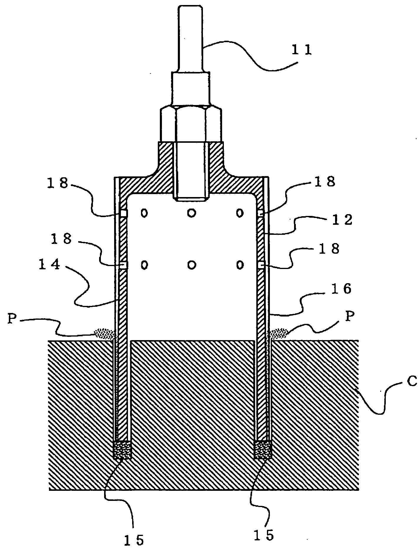
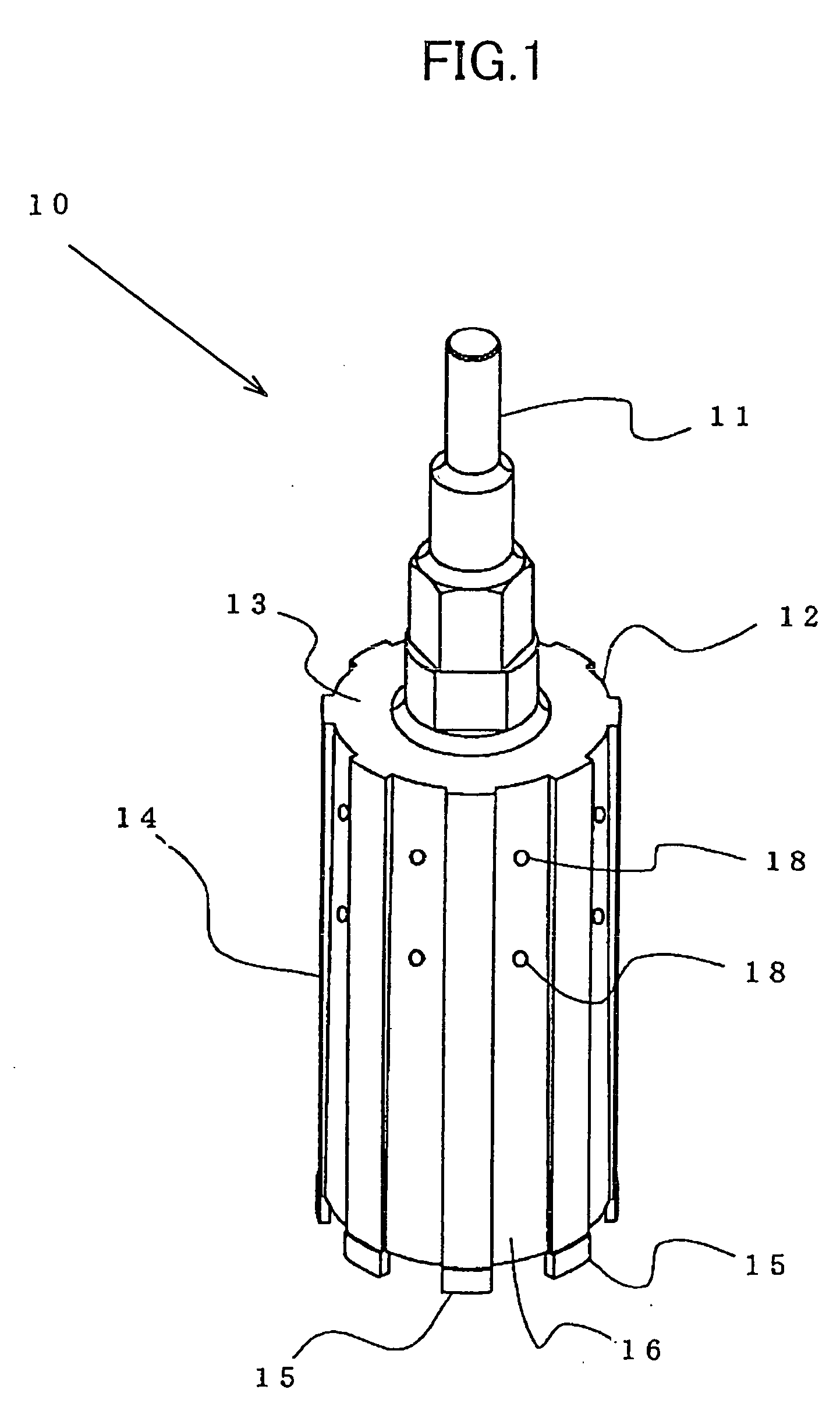
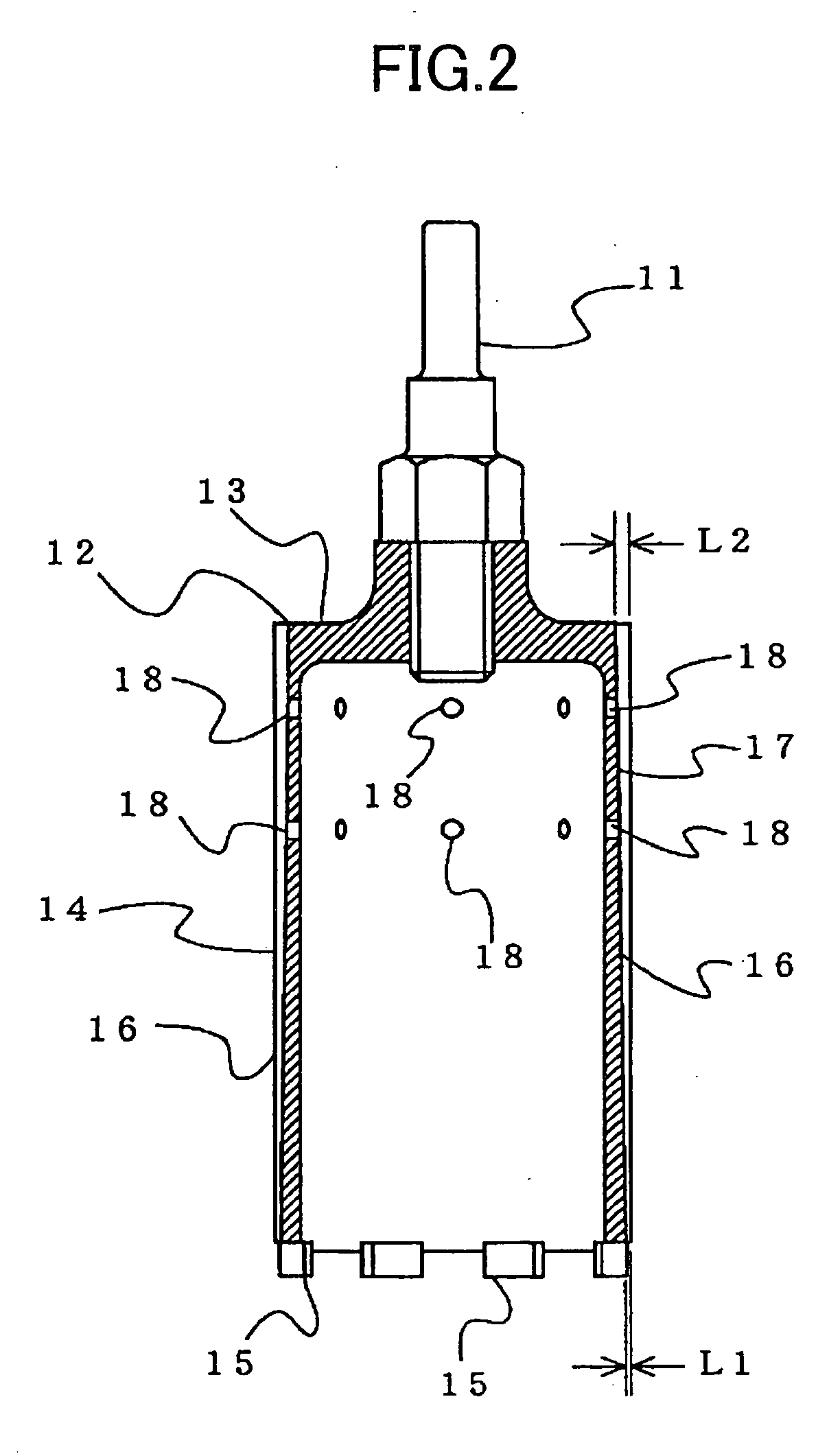
[0032] An explanation will be given of a mode for carrying out the invention based on embodiments shown in the drawings as follows. FIG. 1 shows the core drill 10 according to a first embodiment of the invention which is constituted by the shank 11 coupled to a rotating tool and transmitted with a rotating force similar to the background art, and the drill main body 12 coupled to a lower end portion of the shank 11. The drill main body 12 is constituted by the core main body 14 in a cylindrical shape the upper end portion 13 of which is closed, and a plurality of drilling blades 15 attached to a lower end edge of the core main body 14 at intervals in a circumferential direction. The drilling blade 15 is molded in a tip-like shape by sintering a metal bond mixed with diamond abrasive grains and the drilling blades 15 are bonded to the lower end edge of the core main body 14 by welding at equal intervals in a peripheral direction.

[0033] A plurality of the chip evacuating grooves 16 e...


PUM

PropertyMeasurementUnit
Shapeaaaaaaaaaa
Areaaaaaaaaaaa

Abstract

A plurality of chip evacuating grooves (16, 26, 36, 46a, 46b) in a vertical direction in parallel with a rotational axis of a core main body (14) are formed at an outer peripheral face of the core main body (14) in a circumferential direction from a lower end portion to an upper end portion of the core main body (14) in a cylindrical shape provided with a drilling blade (15) at a lower end edge thereof. Further, a sectional area of the chip evacuating groove (16) is formed to gradually increase from a lower end to an upper end of the core main body (14). Further, a number of projections (52, 62, 70, 72) are formed at the outer peripheral face of the core main body (14) between the chip evacuating grooves.

Description

TECHNICAL FIELD [0001] The present invention relates to a core drill for concrete for boring a comparatively large through hole for piping to concrete, a stone material or the like constituting a wall or a foundation of a building or the like. BACKGROUND ART [0002] A core drill has conventionally been used for boring a comparatively large hole for passing a water pipe, a gas pipe or a pipe for an air conditioner to a wall, a floor, a foundation or the like constituted by concrete, a stone material or the like in constructing or adding or reforming a building. A core drill is attached with drilling blades formed by sintering diamond abrasive grains by a metal bond at a lower end edge of a core main body formed in a cylindrical shape circumferentially at intervals and by pressing the drilling blades to a concrete face and rotating the core main body, a groove in a shape of a circular ring is cut to form at concrete or the like and by cutting the groove gradually deeply, a hole penetra...

Claims


Application Information

Patent Timeline
IPC IPC(8): B28D1/04B23B51/04
CPCB28D1/041
Inventor HIRANUMA, TOSHIOISHIZEKI, MASAKAZUKOSHIBA, TOMOHIROTSUTSUMI, KONICHI
Owner MAX CO LTD
Why Eureka
Try Eureka