Thermal enhanced extended surface tape for integrated circuit heat dissipation

a technology of extended surface tape and integrated circuit, which is applied in the direction of semiconductor devices, semiconductor/solid-state device details, electrical equipment, etc., can solve the problems of increasing the cost of methods, reducing the heat dissipation efficiency of the article, and increasing the heat emissivity of the article. , to achieve the effect of dissipating heat and increasing the heat emissivity of the articl

Inactive Publication Date: 2005-01-27
IBM CORP
View PDF16 Cites 44 Cited by
  • Summary
  • Abstract
  • Description
  • Claims
  • Application Information

AI Technical Summary

Benefits of technology

[0029] In another aspect of the invention an article of manufacture is provided for dissipating heat for integrated circuit and other electronic component devices comprising a flexible flat or preferred corrugated strip of thermal conductive material preferably having an adhesive thereon which adhesive contacts and adheres the strip to the surface of the integrated circuit device. Other articles of manufacture embodiments include a single-faced or a double-faced corrugated thermal conductive material tape preferably with an adhesive thereon. A preferred article of the invention provides a thin coating on the surface of the strip such as a varnish, paint, anodized layer, oxide layer, etc. to increase the heat emissivity of the article.

Problems solved by technology

Existing methods are generally expensive and require improvement in addressing the unit cost issues.
Such methods are expensive and the mechanical properties required at the interface between the heat spreader and the package or IC surface such as adhesion are very important and much material development time and resources are spent on this thereby increasing the cost of the IC device.
These options typically are expensive and such a cost increase in the package becomes prohibitive.
This has limited its acceptance for packaging consideration in many application opportunities such as portable computers and hand held communications devices.
In order to address the increasing power requirements, more expensive packages are needed which reduces the cost performance competitiveness of the package.

Method used


Image

  • Thermal enhanced extended surface tape for integrated circuit heat dissipation
  • Thermal enhanced extended surface tape for integrated circuit heat dissipation
  • Thermal enhanced extended surface tape for integrated circuit heat dissipation

Examples


Embodiment Construction

)

[0039] In describing the preferred embodiment of the present invention, reference will be made herein to FIGS. 1A-7B of the drawings in which like numerals refer to like features of the invention. Features of the invention are not necessarily shown to scale in the drawings.

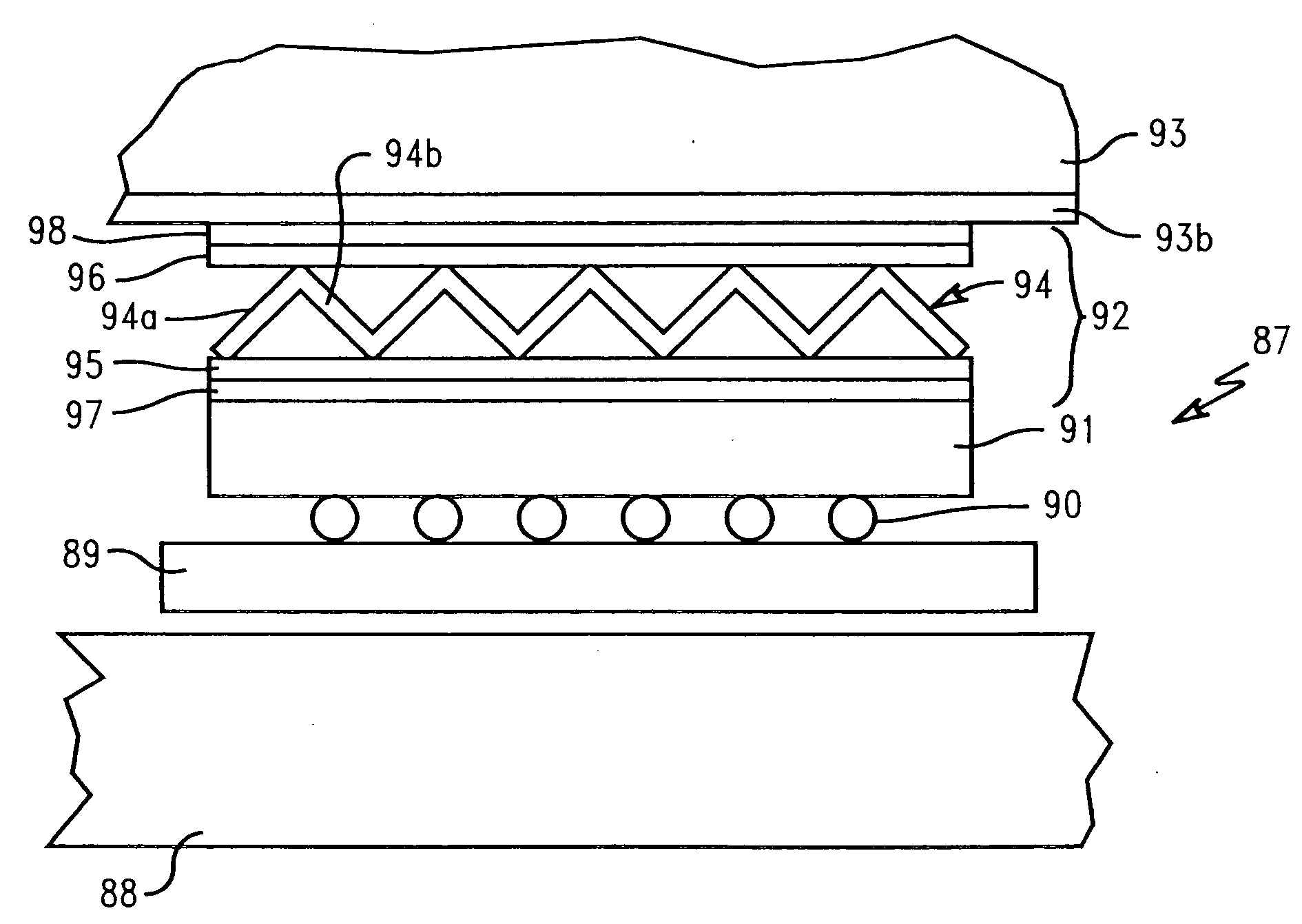
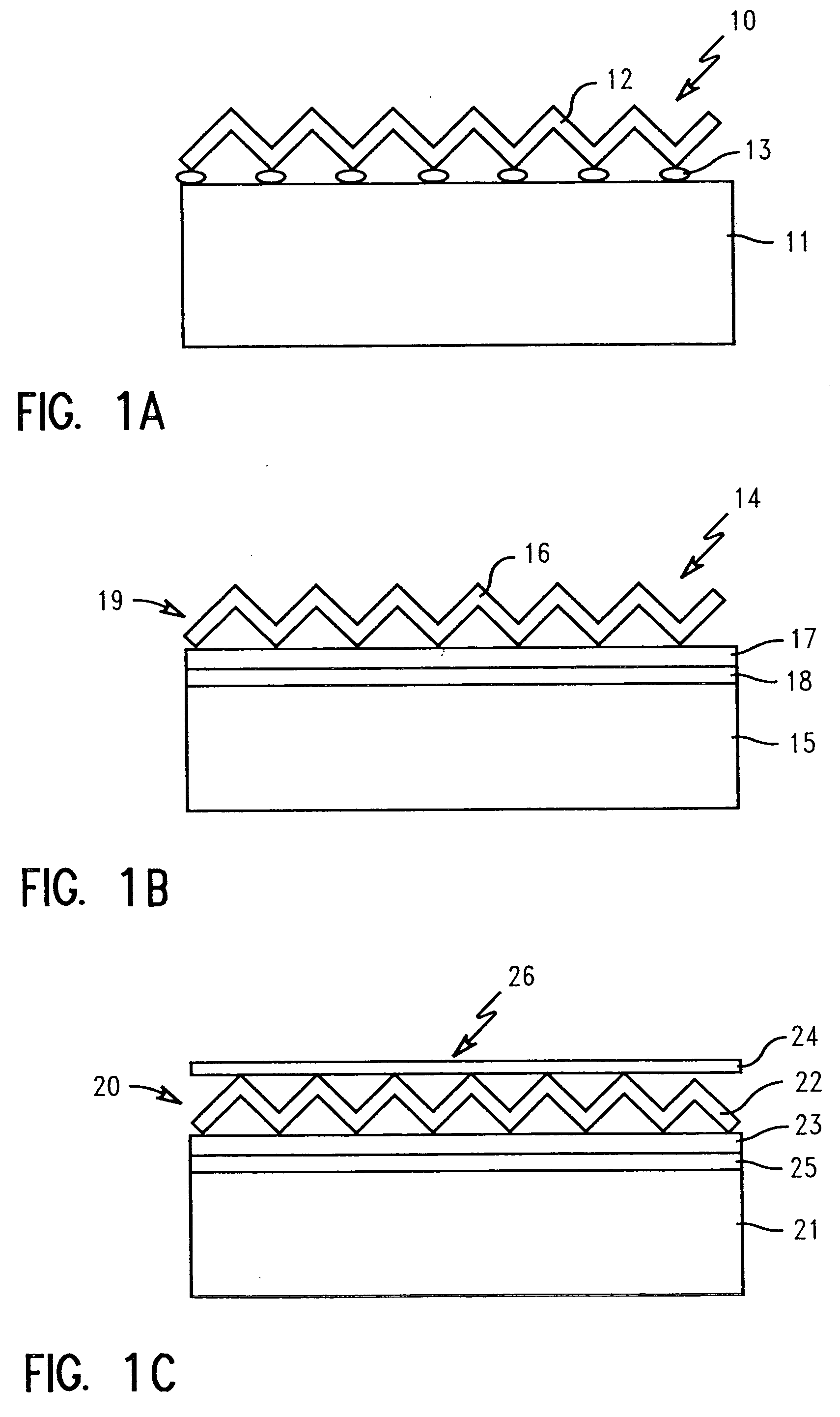
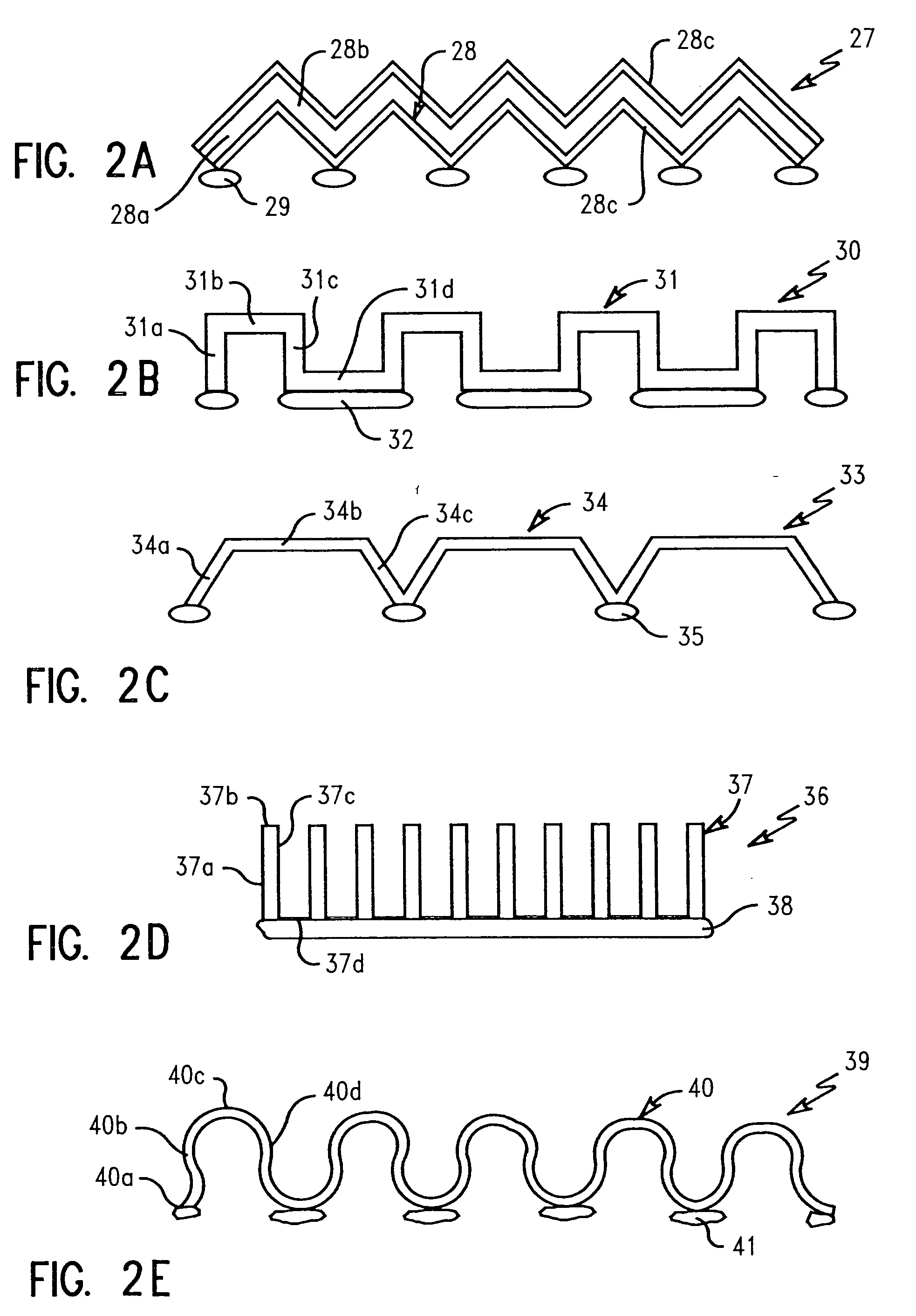
[0040] Broadly stated, this invention comprises using a thermally conductive flexible material preferably with an extended surface area which is applied to the surface of an electronic component to thermally enhance heat dissipation from the electronic component such as IC devices.

[0041] The preferred heat dissipation article of the invention comprises two components. One component is a flexible thermal conductive material strip such as copper, aluminum, gold, silver, phosphor, bronze, beryllium copper and other metal or thermal conductive materials which has been preferably corrugated. The other component is an adhesive material which can be either a pressure sensitive or other kind known in the art. By using ...


PUM


Abstract

A thermal conductive tape article is provided which is adhered to the surface of an integrated circuit device to dissipate heat from the device. The thermal conductive tape article is preferably corrugated and may have a number of configurations providing an expanded surface area. The corrugated tape article may also have a metal strip bonded to one or both sides of the tape article to form a single-faced or double-faced corrugated tape article. The tape article is preferably made of copper or aluminum.

Description

BACKGROUND OF THE INVENTION [0001] 1. Field of the Invention [0002] This invention relates to dissipating heat from electronic components and, more particularly, to a thermal conductive tape having an extended surface area which is applied to the surface of an integrated circuit for heat dissipation. [0003] 2. Description of Related Art [0004] As the need for power (heat) dissipation of electronic components such as integrated circuits (IC) and particularly lower power applications of less than 10 watts continues to increase, it is of great commercial interest to enhance packaging thermal characteristics. Existing methods are generally expensive and require improvement in addressing the unit cost issues. For convenience, the following description will be directed to semiconductors (IC's), however, it will be appreciated by those skilled in the art that the invention can be used for any type electronic component. [0005] Traditional methods to enhance packaging thermal characteristics...

Claims


Application Information

Patent Timeline
Patent Type & Authority Applications(United States)
IPC IPC(8): H01L23/367
CPCH01L23/3672H01L2224/73253H01L2224/16H01L2924/00014H01L2224/0401
Inventor CORTI, WILLIAM D.LONG, DAVID C.MARSH, JOSEPH O.SCANZANO, FRANCIS X.WON, MICHAELYUAN, TSORNG-DIH
Owner IBM CORP
Why Eureka
Try Eureka