Multi-grid ion beam source for generating a highly collimated ion beam

a multi-grid, ion beam technology, applied in the direction of ion beam tubes, machines/engines, instruments, etc., can solve the problems of insufficient ion beam current reduction, no experimental data available, and uniform spacing between the grids of the ion beam sour

Inactive Publication Date: 2005-01-27
VEECO INSTR
View PDF29 Cites 13 Cited by
  • Summary
  • Abstract
  • Description
  • Claims
  • Application Information

AI Technical Summary

Benefits of technology

[0008] Against this backdrop, the present invention has been developed. The present invention relates to a multi-grid ion beam source having a focus grid positioned between the acceleration grid and the shield grid or between two shield grids. In one embodiment, the focus grid has a large positive potential, resulting in an of

Problems solved by technology

However, the existing 4-grid optics system requires the new acceleration grid to be contoured (instead of flat), resulting in non-uniform spacing from center-to-edge between the grids in the ion beam source.
No experimental data is available to support the claim

Method used


Image

  • Multi-grid ion beam source for generating a highly collimated ion beam
  • Multi-grid ion beam source for generating a highly collimated ion beam
  • Multi-grid ion beam source for generating a highly collimated ion beam

Examples


Embodiment Construction

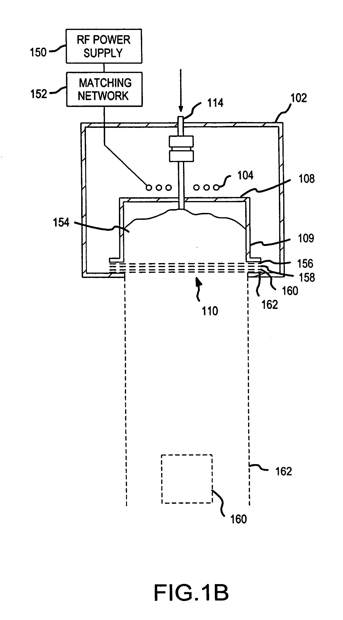
[0029] In an embodiment of the present invention, a 4-grid ion beam source generates a highly collimated ion beam. The 4-grid optics system comprises an ordered set of four grids: extraction grid, an acceleration grid, a focus grid, and a shield grid, progressing from the plasma source (e.g., a plasma chamber) toward a target. In one embodiment, the focus grid has high positive potential. In another embodiment, the focus grid has a high negative potential. In other embodiments, 5-grid optics systems are provided, including one embodiment with a negative biased focus grid and another embodiment with a positive biased focus grid. Adding additional grid to the described configurations will not depart from the scope of the present invention.

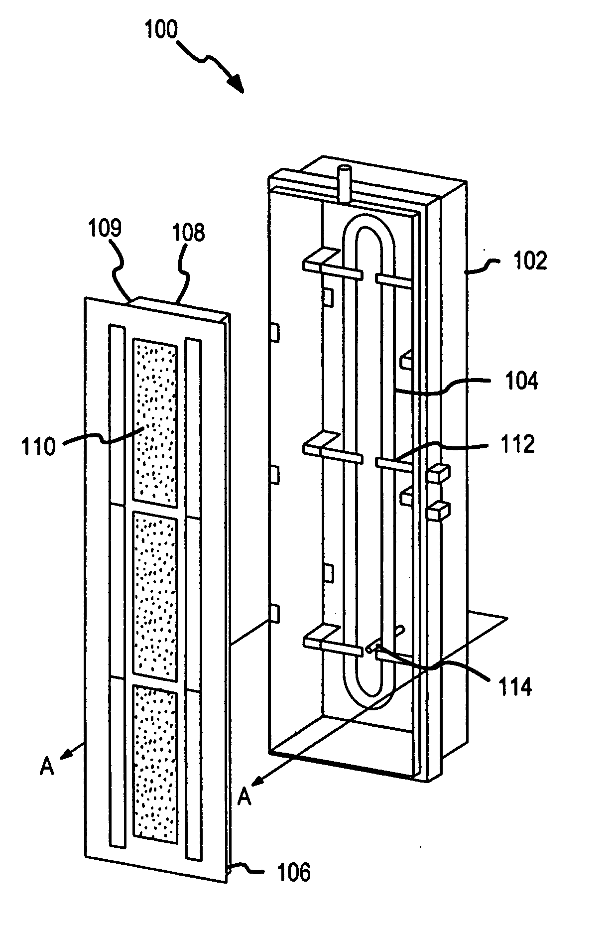
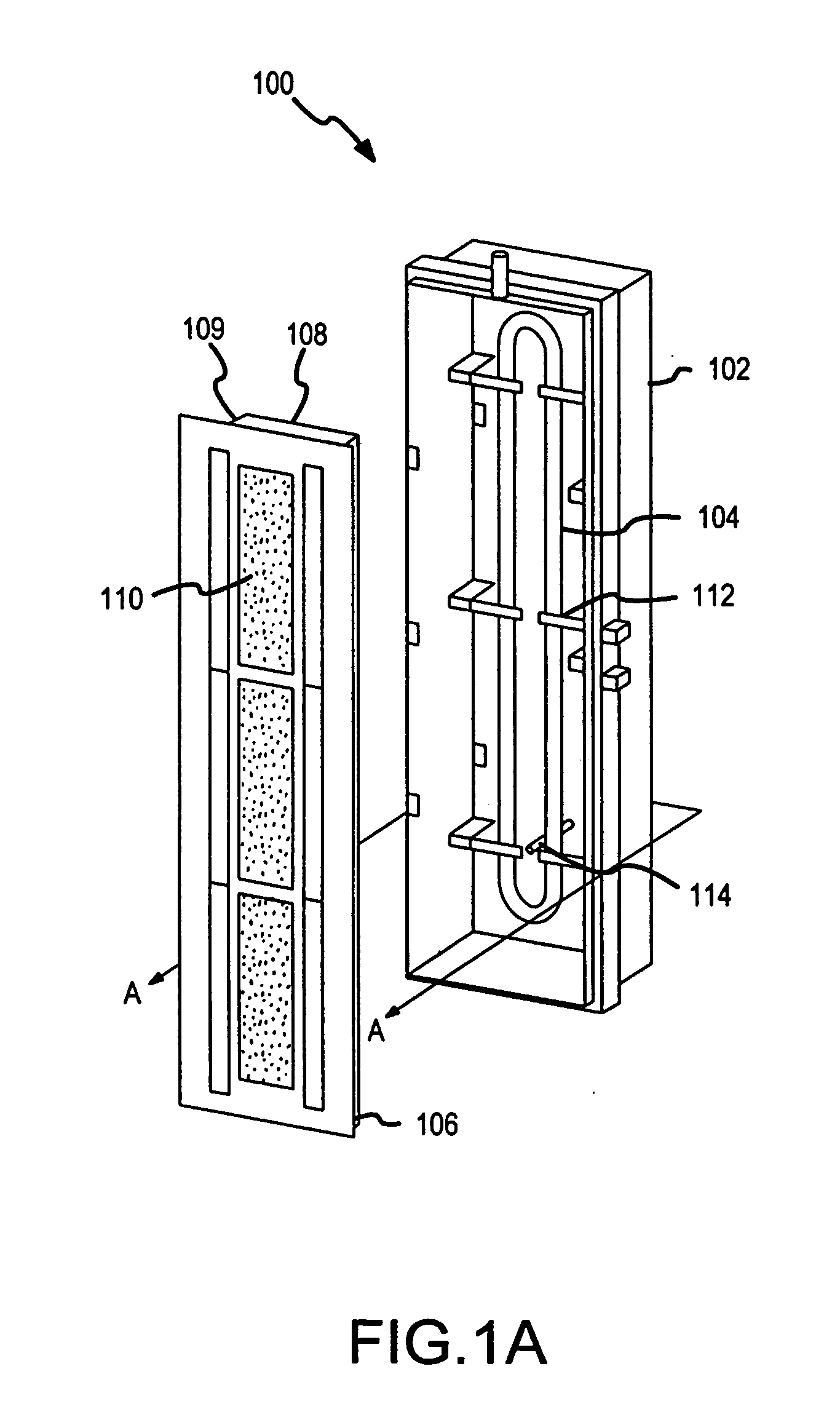
[0030]FIG. 1A depicts a generalized three-dimensional, exploded view of a rectangular 4-grid ion beam source 100 in an embodiment of the present invention. In this embodiment, an RF coil is used to generate a plasma discharge. A direct current (DC) ...


PUM


Abstract

A multi-grid ion beam source has an extraction grid, an acceleration grid, a focus grid, and a shield grid to produce a highly collimated ion beam. A five grid ion beam source is also disclosed having two shield grids. The extraction grid has a high positive potential and covers a plasma chamber containing plasma. The acceleration grid has a non-positive potential. The focus grid is positioned between the acceleration grid and the shield grid. The combination of the extraction grid and the acceleration grid extracts ions from the plasma. The focus grid acts to change momentum of the ions exiting the acceleration grid, focusing the ions into a more collimated ion beam than previous approaches. In one embodiment, the focus grid has a large positive potential. In another embodiment, the focus grid has a large negative potential.

Description

FIELD OF THE INVENTION [0001] This invention generally relates to ion beam sources, and, in particular, to generating highly collimated ion beamlets by utilizing a set of optics grids in an ion beam source. BACKGROUND OF THE INVENTION [0002] Ion beams come in many varieties and have many industrial applications. For example, a collimated low-power ion beam may be employed to align inorganic materials in a liquid crystal display. Alternatively, a collimated high-power ion beam may be employed to ion etch a surface or propel a vehicle in space. A highly collimated ion beam, which has minimum off-axis velocity components, is generally desirable in many broad beam ion source applications. Other applications of collimated ion beams include without limitation ion milling and aligning superconducting YBa2Cu3O7 crystals as they grow using Ion Beam Assisted Deposition techniques to increase the current carrying capability of High Temperature Superconducting tapes. [0003] An “ion” is a charge...

Claims


Application Information

Patent Timeline
IPC IPC(8): H01J27/02
CPCH01J27/024
Inventor WAHLIN, ERIK KARL KRISTIAN
Owner VEECO INSTR
Why Eureka
Try Eureka