Signal processing device, signal processing method, delta-sigma modulation type fractional division pll frequency synthesizer, radio communication device, delta-sigma modulation type d/a converter

Inactive Publication Date: 2005-01-27
PANASONIC CORP
View PDF5 Cites 29 Cited by
  • Summary
  • Abstract
  • Description
  • Claims
  • Application Information

AI Technical Summary

Benefits of technology

An object of the present invention is to suppress concentration of quantization noise at a particular frequency.
To achieve the above-described object, the present invention uses a signal processing device which has a configuration including, in addition to a delta-sigma modulator, a dither circuit, located between a digital input and

Problems solved by technology

However, it has been pointed out as a problem that as a result of concentration of quantization noise at a particular frequency when the ΔΣ modulator receives a particular F value (e.g., F=2n−1), a spurious signal is generated.
Accordingly, two problems, i.e., (1) a problem

Method used


Image

  • Signal processing device, signal processing method, delta-sigma modulation type fractional division pll frequency synthesizer, radio communication device, delta-sigma modulation type d/a converter
  • Signal processing device, signal processing method, delta-sigma modulation type fractional division pll frequency synthesizer, radio communication device, delta-sigma modulation type d/a converter
  • Signal processing device, signal processing method, delta-sigma modulation type fractional division pll frequency synthesizer, radio communication device, delta-sigma modulation type d/a converter

Examples


Embodiment Construction

<The Configuration of a Cellular Phone>

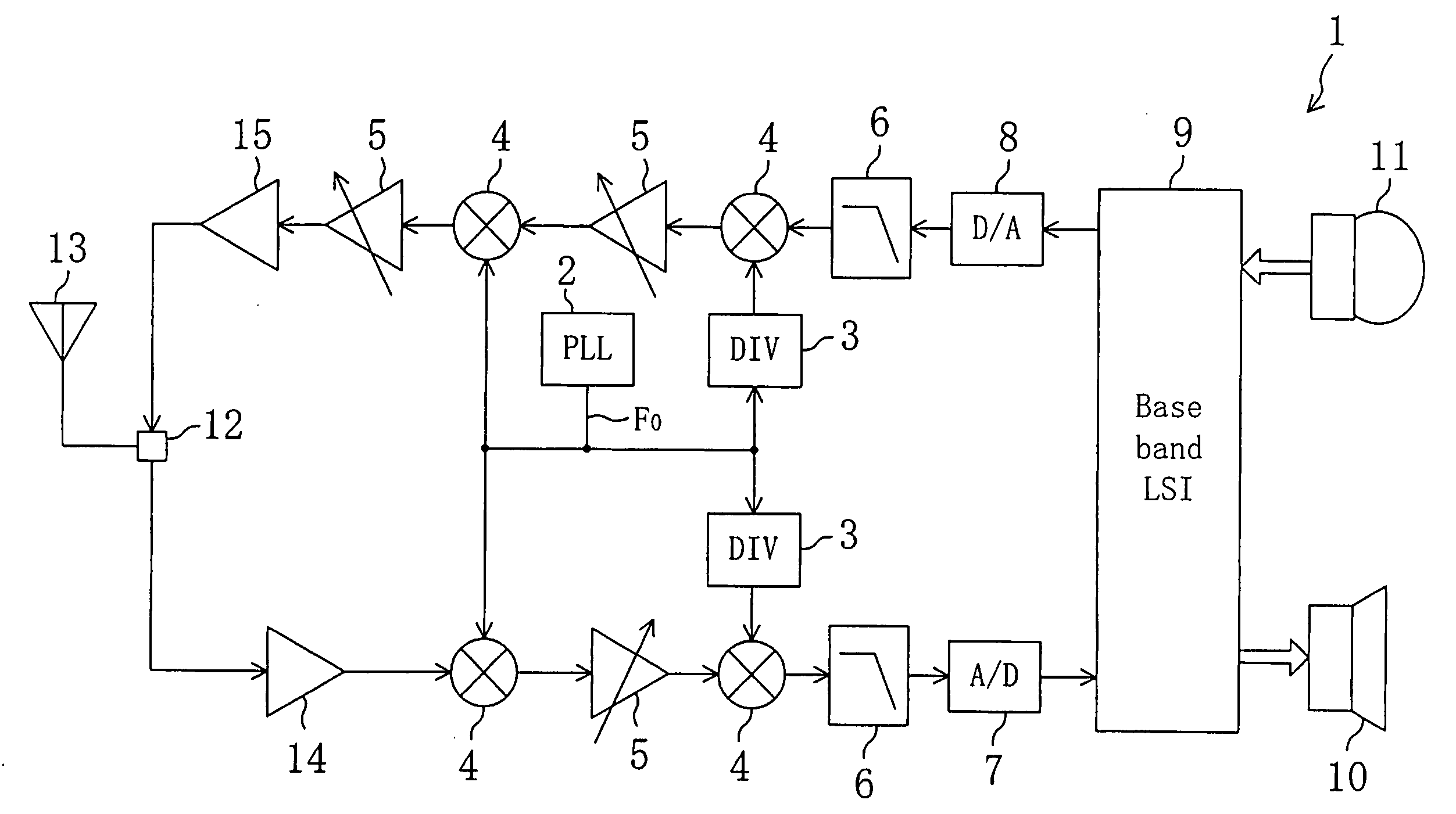
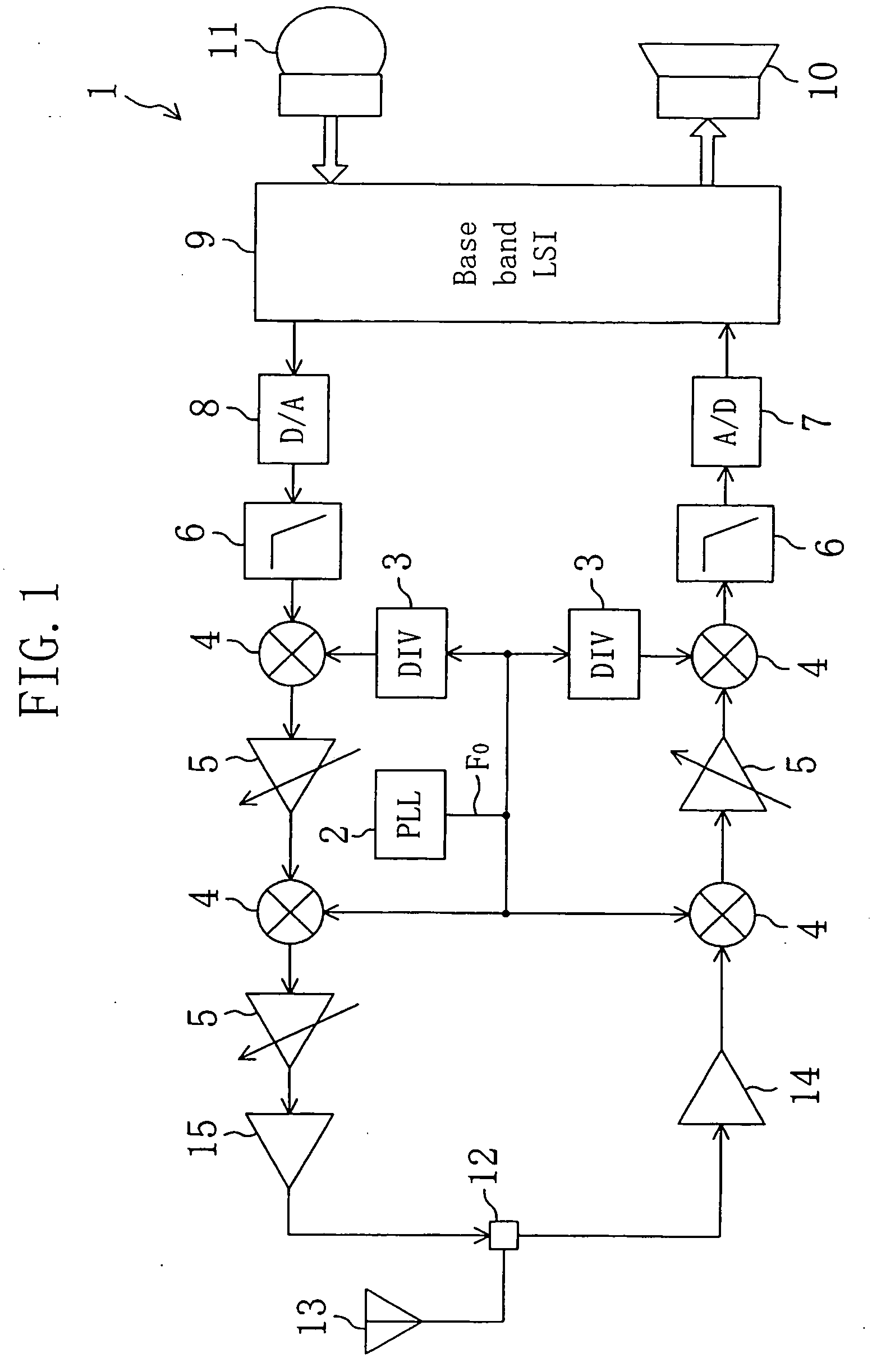
FIG. 1 is a block diagram illustrating a cellular phone (radio communication device) to which a ΔΣ modulation fractional frequency division PLL frequency synthesizer according to the present invention is applied. The cellular phone shown in FIG. 1 includes a ΔΣ modulation fractional frequency division PLL frequency synthesizer 2, a frequency divider (DIV) 3, a modulator / demodulator (mixer) 4, a gain control amplifier (GCA) 5, a low-pass filter (LPF) 6, an analog / digital (A / D) converter 7, an digital / analog (D / A) converter 8, a base band LSI 9, a speaker 10, microphone 11, a changing switch 12, an antenna 13, a low noise amplifier 14 and a driver amplifier 15. Fo denotes an output signal of the ΔΣ modulation fractional frequency division PLL frequency synthesizer.

<The Configuration of the PLL Frequency Synthesizer 2>

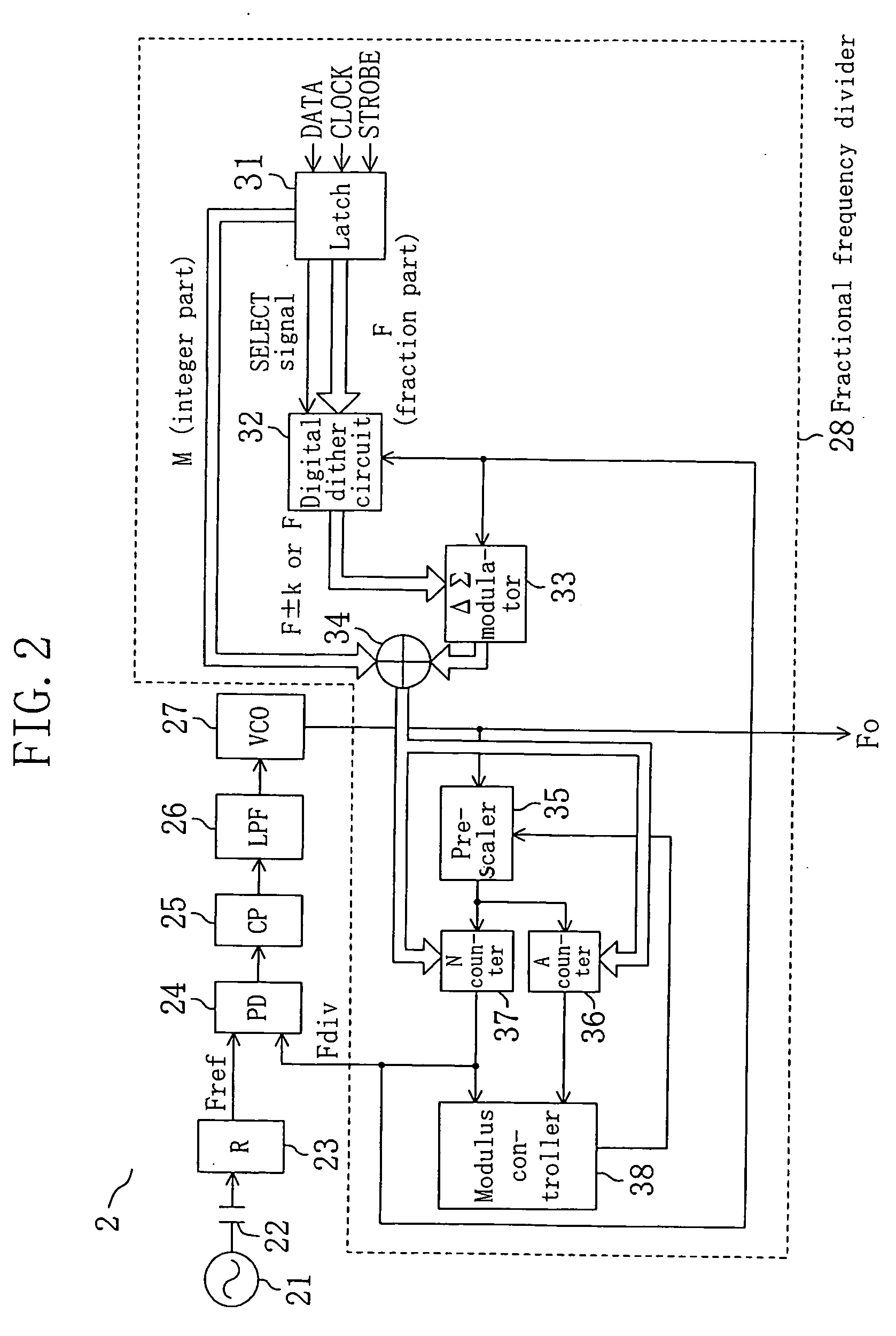
FIG. 2 is a block diagram illustrating an internal configuration of the ΔΣ modulation fractional frequency division PLL ...


PUM


Abstract

A fractional frequency divider (28) includes a latch (31) for holding frequency division data, a ΔΣ modulator (33), a digital dither circuit (32) for receiving a digital input F representing fraction part of the frequency division data from the latch (31) and supplying a digital output alternately changing between F+k and F−k (where k is an integer) or a F value itself to the ΔΣ modulator (33), and circuit means (34 through 38) for executing fractional frequency division based on integer part (M value) of the frequency division data and an output of the ΔΣ modulator (33). The digital dither circuit (32) is useful for suppressing a spurious signal generated as a result of concentration of quantization noise at a particular frequency when the ΔΣ modulator (33) receives a particular F value (e.g., F=2n−1).

Description

TECHNICAL FIELD The present invention relates to a signal processing device, a signal processing method, a delta-sigma modulation type fractional frequency division PLL frequency synthesizer, a radio communication device and a delta-sigma modulation type D / A converter. BACKGROUND ART A delta-sigma (ΔΣ) modulator has a circuit configuration which performs feedback of quantization noise generated in an output to an input via a delayer and sometimes is called “sigma-delta (ΣΔ) modulator” or “noise shaper” because of its function of biasing quantization noise to the high frequency band. When a frequency synthesizer including a phase locked loop (PLL) is used for a radio communication device such as a cellular phone, in order to ensure many available bands, it is required to change an output frequency with a smaller step size than the frequency of a reference signal. As a frequency synthesizer to meet this requirement, a ΔΣ modulation fractional frequency division PLL frequency synthe...

Claims


Application Information

Patent Timeline
IPC IPC(8): H03M1/20H03L7/183H03L7/197H03M1/08H03M3/00H03M3/02H03M7/00H03M7/36H04B14/06
CPCH03L7/1978H03M7/3042H03M7/3008
Inventor NAGASO, YOICHISAEKI, TAKAHARU
Owner PANASONIC CORP
Why Eureka
Try Eureka