Exposure with intensity balancing to mimic complex illuminator shape

a technology of intensity balance and illumination, applied in the field of optimizing the conditions of illumination of lithographic apparatus, can solve the problems of reducing the depth of focus, exceeding the resolution limit of currently available lithographic techniques, and repeatedly exceeding the limits of optical lithography once accepted

Inactive Publication Date: 2005-01-27
ASML NETHERLANDS BV
View PDF19 Cites 64 Cited by
  • Summary
  • Abstract
  • Description
  • Claims
  • Application Information

AI Technical Summary

Problems solved by technology

As the demand to image smaller and smaller features in the semiconductor manufacturing process has continued unabated, the limitations of optical lithography that were once accepted have been exceeded repeatedly.
As the semiconductor industry moves into the deep submicron regime, the resolution limit of currently available lithographic techniques is being reached due to a decrease in the depth of focus, difficulty in the design of projection system and complexities in the projection system fabrication technology.
Such an approach results in a significant loss in intensity available to the mask, lowering throughput and making the approach less than desirable.
Additionally, the two or four circular openings need to be designed specifically for certain mask geometry and pitch and do not improve the performance of other geometry sizes and spacings.
However, the creation of complex source shapes to optimize the optical transfer of a given mask pattern remains a slow and expensive process.
Even the production of small sigma poles, e.g. smaller than 0.1, with commercially available beam shapers can potentially be complicated.
Unfortunately, these custom elements are expensive and cannot generally be modified if they do not provide the intended results.

Method used


Image

  • Exposure with intensity balancing to mimic complex illuminator shape
  • Exposure with intensity balancing to mimic complex illuminator shape
  • Exposure with intensity balancing to mimic complex illuminator shape

Examples


Embodiment Construction

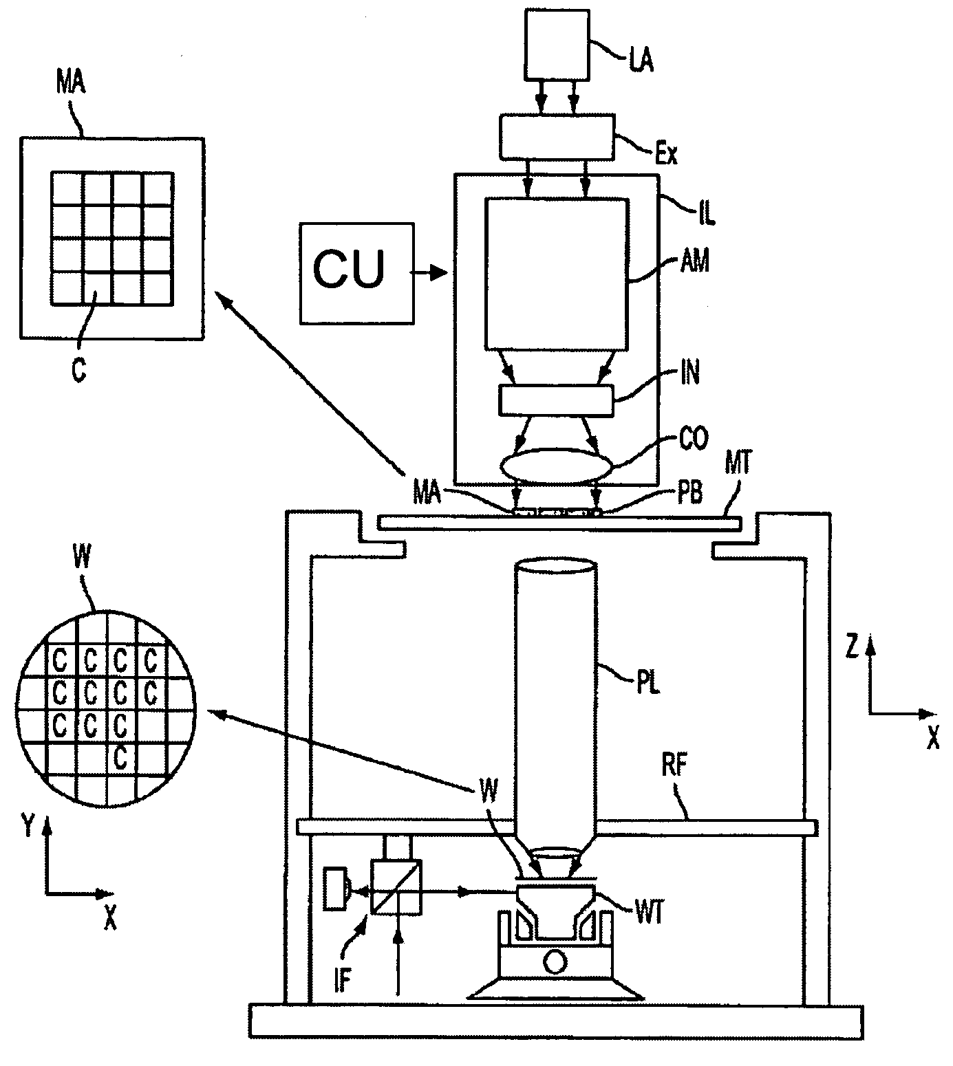
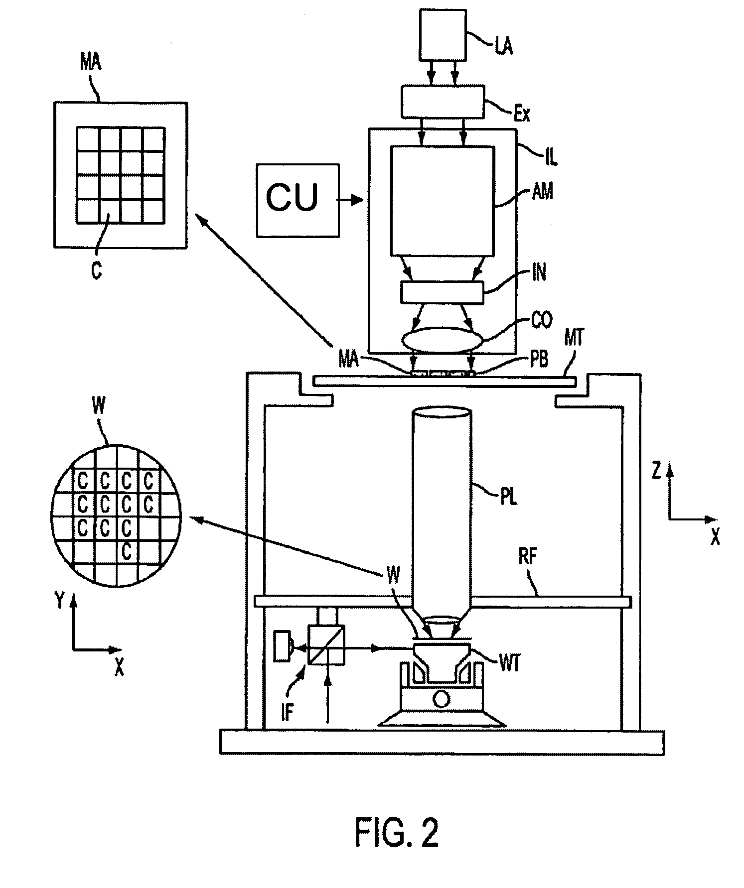
Embodiments of the invention include methods and apparatus to improve a lithographic process without resorting to the use of expensive custom apertures or optics to produce complex source shapes. Since the image of the mask pattern on the substrate is the sum of the images of all the individual source points in the illuminator, optimization of the optical transfer of the mask pattern may be done using a single or multiple illuminations. Thus, it is possible to deliver an integrated image of the mask pattern all at once or in temporally separated exposures.

In an embodiment of the invention, the method for optimizing the optical transfer of the mask pattern includes determining a plurality of illumination arrangements for a pupil plane of the illuminator, each of the plurality of illumination arrangements being determined to improve a respective lithographic performance response parameter when illuminating the mask pattern, and adjusting an intensity of a first illumination arrange...


PUM

PropertyMeasurementUnit
optical transferaaaaaaaaaa
transmissionaaaaaaaaaa
variable threshold resist modelaaaaaaaaaa

Abstract

A method for optimizing the optical transfer of a mask pattern onto a substrate using a lithographic apparatus, the lithographic apparatus including an illuminator configured to illuminate the mask pattern, the method including determining a plurality of illumination arrangements for a pupil plane of the illuminator, each of the plurality of illumination arrangements being determined to improve a respective lithographic performance response parameter when illuminating the mask pattern; and adjusting an intensity of a first illumination arrangement of the plurality of illumination arrangements relative to a second illumination arrangement of the plurality of illumination arrangements, the mask pattern to be illuminated with the first and second illumination arrangements. The mask pattern may be illuminated at least once for each of the first and second illumination arrangements or all at once with at least the first illumination arrangement and the second illumination arrangement.

Description

FIELD The present invention relates to a method for optimizing the conditions of illumination of a lithographic apparatus. BACKGROUND A lithographic apparatus is a machine that applies a desired pattern onto a target portion of a substrate. Lithographic apparatus can be used, for example, in the manufacture of integrated circuits (ICs). In that circumstance, a patterning device (or patterning structure), which is alternatively referred to as a mask or a reticle, may be used to generate a circuit pattern corresponding to an individual layer of the IC, and this pattern can be imaged onto a target portion (e.g. including part of, one or several dies) on a substrate (e.g. a silicon wafer) that has a layer of radiation-sensitive material (resist). In general, a single substrate will contain a network of adjacent target portions that are successively exposed. Known lithographic apparatus include so-called steppers, in which each target portion is irradiated by exposing an entire pattern...

Claims


Application Information

Patent Timeline
Patent Type & Authority Applications(United States)
IPC IPC(8): G03F7/20
CPCG03F7/701G03F7/705G03F7/70108
Inventor HANSEN, STEVEN GEORGE
Owner ASML NETHERLANDS BV
Why Eureka
Try Eureka