Fiber array interferometer for inspecting glass sheets

a fiber array and glass sheet technology, applied in the field of glass sheet inspection, can solve the problems of product rejection, poor resolution, and fast human inspection

Inactive Publication Date: 2005-01-27
CORNING INC
View PDF17 Cites 43 Cited by
  • Summary
  • Abstract
  • Description
  • Claims
  • Application Information

AI Technical Summary

Benefits of technology

In accordance with one of its aspects, the invention provides a method for inspecting a surface (11) of a sheet of material (e.g., a glass sheet 31 having an optical reflectivity of less than 10% and typically less than 5%) comprising: (a) providing a plurality of optical fibers (15), each fiber having a cleaved end (19), said cleaved ends being arranged in an array (13) which has a longitudinal axis (e.g., the x-axis in FIG. 2); (b) positioning said array (13) with respect to said surface (11) so that each optical fiber (15) is associated with a region (27) of the surface (11); (c) for each optical fiber (15), introducing coherent light (49) into the fiber to produce reference and measurement beams which optically interfere with eac

Problems solved by technology

Substrate defects, such as, glass chips, scratches, blisters, inclusions, and stains, can readily lead to product rejects.
Human inspection is very fast but has poor resolution, at no better than 50 microns, and poor repeatability.
However, increases in resolution for such systems has meant slower inspection speeds

Method used


Image

  • Fiber array interferometer for inspecting glass sheets
  • Fiber array interferometer for inspecting glass sheets
  • Fiber array interferometer for inspecting glass sheets

Examples


Embodiment Construction

In its preferred embodiments, the present invention relates to the inspection of glass sheets and, in particular, to the inspection of LCD glass sheets to determine if defects are present which make the sheet unsuitable for use in the manufacture of liquid crystal displays.

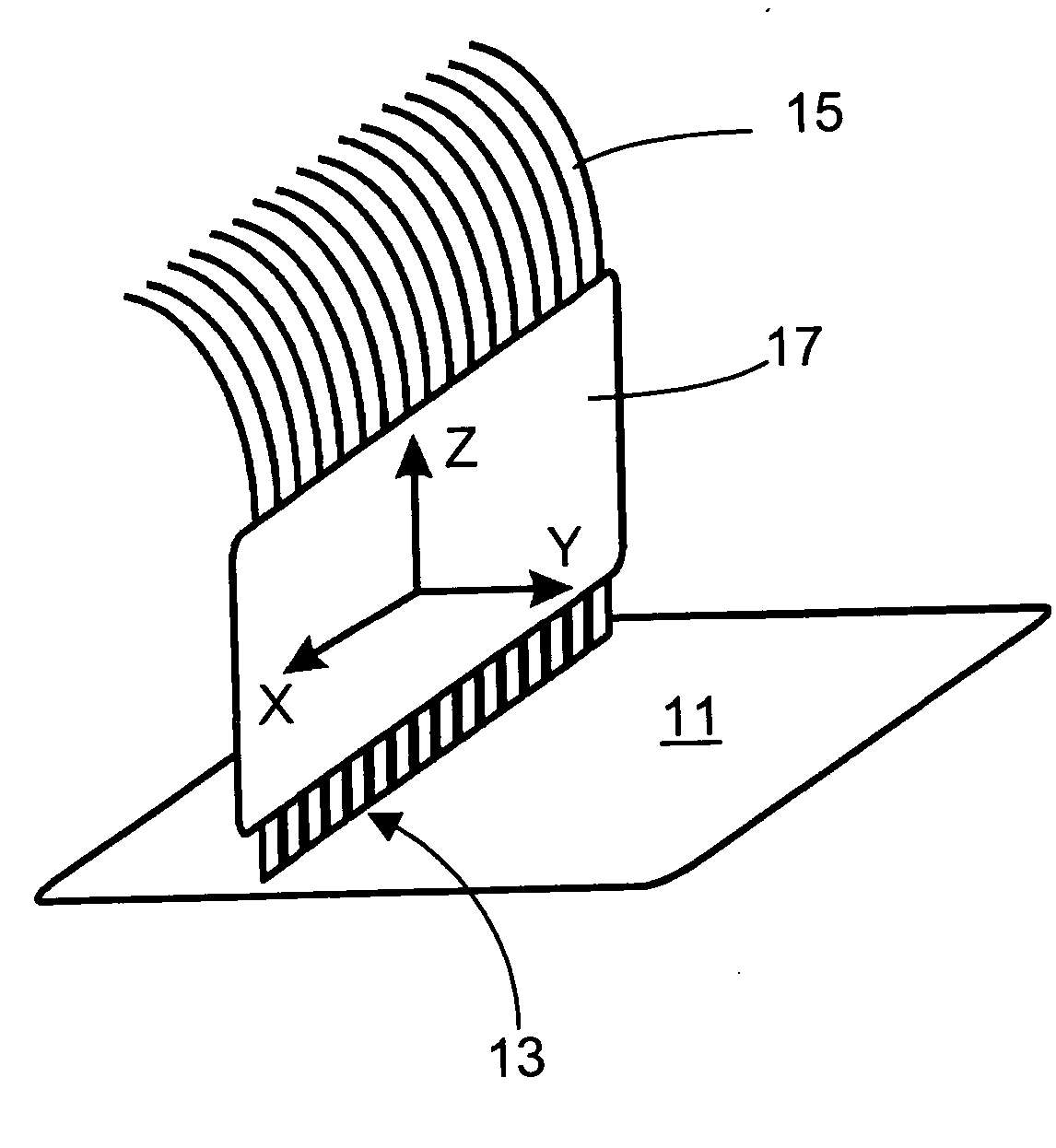
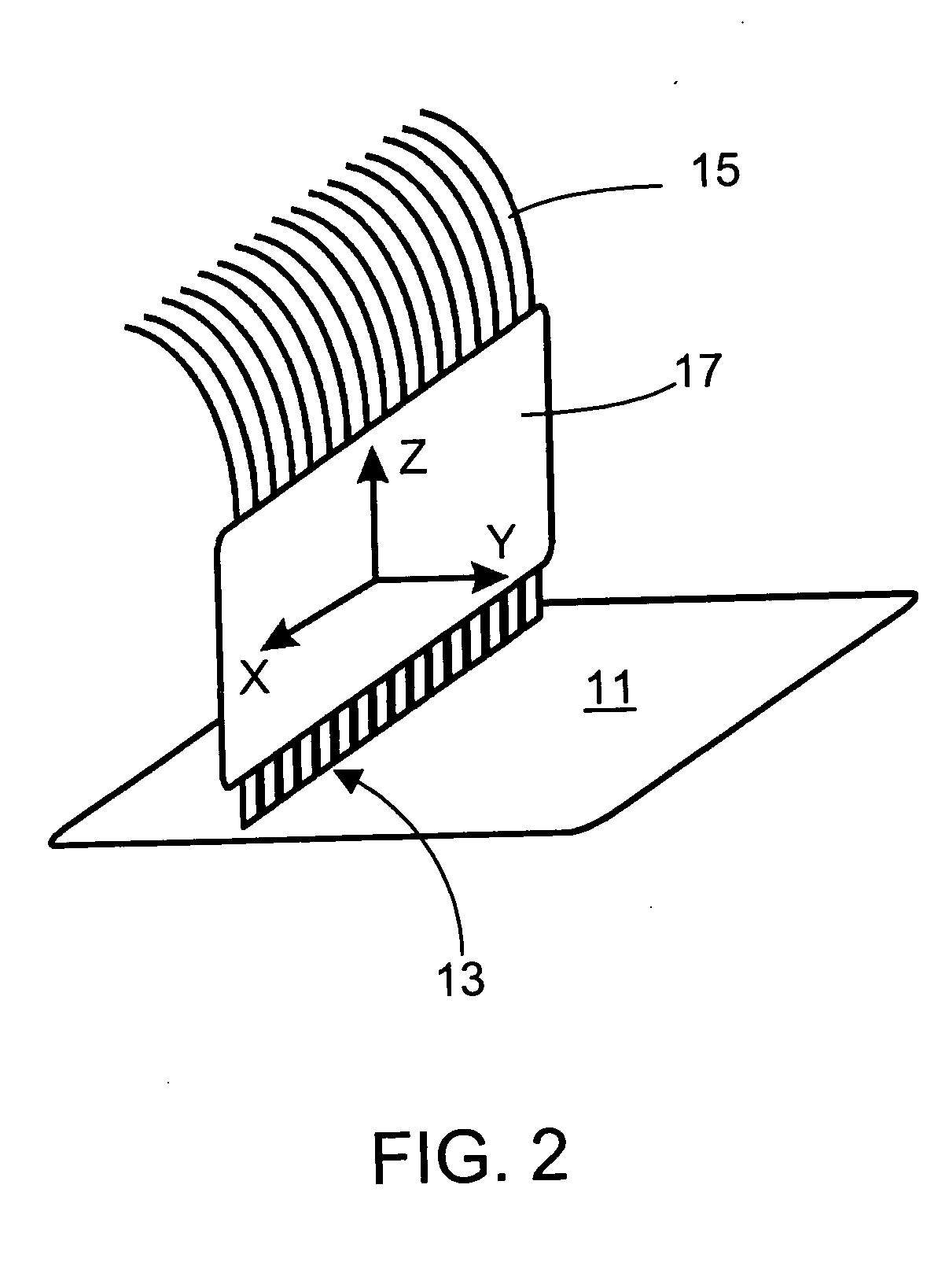
In overview, the invention employs a parallel array of all-fiber interferometers (arranged in a Fizeau or Fabry-Perot configuration) which is scanned along an axis normal to the plane of the array (e.g., the array is scanned along the y-axis in FIG. 2; see below). For light having a wavelength λ, height resolution can be better than λ / 1000 and spatial resolution can be around λ, which is comparable to the spatial resolution achieved with conventional optical microscopy. These height and spatial resolutions make the invention particularly well suited for finding localized, small variations in the height of the surface of the glass, i.e., they make the invention particularly well suited to finding defects. Compar...


PUM


Abstract

A major surface (11) of a large substrate (31), e.g., a sheet of transparent LCD glass, is inspected for defects with high resolution and height sensitivity using an array (13) of optical fibers (15). For each fiber (15), a reference beam of coherent light, which has reflected from the fiber's cleaved end (19), interferes with a measurement beam of coherent light, which has exited the cleaved end (19), reflected from the surface (11), and reentered the fiber (15). The intensity of the interference signal serves as a measure of the distance between the cleaved end (19) and the region (27) of the surface (11) with which the fiber (15) is associated. Insight into the polarization properties of the defect, as an aid to accurate classification, can be obtained by independently monitoring the polarization states of two orthogonal measurement beams.

Description

FIELD OF THE INVENTION This invention relates to the inspection of glass sheets and, in particular, to the inspection of glass sheets of the type used as substrates in liquid crystal displays (LCDs). BACKGROUND OF THE INVENTION As is well known, liquid crystal displays (LCDs) are composed of a layer of a liquid crystal material sandwiched between two thin glass sheets. Typically, one of the glass sheets serves as a substrate upon which electrical components, e.g., thin film transistors (TFTs), are formed to define the individual pixels of the display. LCDs of this type are known as active matrix liquid crystal displays or AMLCDs. Thin film transistors formed on glass substrates have narrow performance tolerances. Substrate defects, such as, glass chips, scratches, blisters, inclusions, and stains, can readily lead to product rejects. In particular, the thin contact leads for the TFTs are especially sensitive to sharp variations in height, which can cause open circuits. FIGS. 1A a...

Claims


Application Information

Patent Timeline
IPC IPC(8): G01N21/95G01N21/958G02F1/1362
CPCG01N21/958G02F2001/136254G01N2021/9513G01N2021/4719G02F1/136254
Inventor LEBLANC, PHILIP R.
Owner CORNING INC
Why Eureka
Try Eureka