Thrust needle roller bearing

a needle roller bearing and needle technology, applied in the direction of needle bearings, shafts and bearings, rotary machine parts, etc., can solve the problems of insufficient durability, deterioration of fuel consumption, and increased use conditions, so as to reduce friction between the retainer and the needle roller. , the effect of high durability

Inactive Publication Date: 2005-01-27
NTN CORP
View PDF9 Cites 23 Cited by
  • Summary
  • Abstract
  • Description
  • Claims
  • Application Information

AI Technical Summary

Benefits of technology

[0012] An object of the invention is to provide a thrust needle roller bearing, which is light, can reduce friction between a retainer and needle rollers, and has high durability.
[0014] According to the thrust needle roller bearing of the invention, since the retainer is made of the synthetic resin, which is much lighter than iron, the thrust needle roller bearing has a lightweight structure. The retainer made of the synthetic resin can ensure a strength required in the retainer. Since a friction coefficient between the iron and the synthetic resin is much smaller than that between iron and iron, friction between the needle roller and the retainer is small (i.e., self-lubricity is good). Thereby, a torque required for rolling the roller can be small. Since metallic sounds due to contact between metal members do not occur during rolling of the needle rollers, noises can be small.
[0015] Since the needle rollers are arranged in multiple rows within the retainer, this arrangement reduces a difference in revolution peripheral speed between a radially outer portion and a radially inner portion of the needle roller so that heat generation from contact portions can be suppressed, and the surface damage (smearing) and surface-starting peeling can be prevented. Consequently, the thrust needle roller bearing can have high durability.
[0023] Since the polyphenylene sulfide does not hydrolyze owing to its properties, the retainer hardly absorbs moisture when the thrust needle roller bearing is used in an atmosphere having a high moisture content. Therefore, change in size and lowering in strength of the retainer can be prevented. Since the glass fibers have a high mechanical strength, the retainer containing the glass fibers can have an improved strength and an improved heat resistance. The synthetic resin containing the glass fibers in the polyphenylene sulfide can be easily melted by heating, and can be easily solidified by cooling. Therefore, the synthetic resin thus formed can be suitably used for manufacturing the retainer by injection molding. Since the synthetic resin containing the glass fibers in the polyphenylene sulfide has good resistances against chemicals and oil, the thrust needle roller bearing can be used in an atmosphere containing chemicals or oil, which may adhere thereto.
[0025] This structure remarkably reduces a frictional resistance between the roller and the retainer as well as the frictional resistance between the neighboring rollers, and thus suppresses drilling friction, which may be caused by friction due the contact between such members. The drilling friction means an abnormal friction, which is caused by such operations that a centrifugal force pushes the end surface of the needle roller against a wall surface of the pocket in the retainer, and the rotation of each needle roller about its own axis further causes the contact of the needle roller.
[0027] The thrust needle roller bearing in the bearing structure, which bears the thrust load of the compressor in the air conditioner of the automobile, is used under severe conditions such as driving with lean lubrication or high-speed rotation. Therefore, the thrust needle roller bearing according to the invention can be suitably used because it is light, and can suppress friction between the retainer and the needle rollers.

Problems solved by technology

Conditions of use are becoming more severe due to driving with lean lubrication or high-speed rotation.
Thus, thrust needle roller bearing 50 is primarily made of iron so that it suffers from a problem of a large weight.
This deteriorates the fuel consumption.
Since these phenomena are liable to occur in the conventional thrust needle roller bearing, it may also suffer from insufficient durability.

Method used


Image

  • Thrust needle roller bearing
  • Thrust needle roller bearing
  • Thrust needle roller bearing

Examples


first embodiment

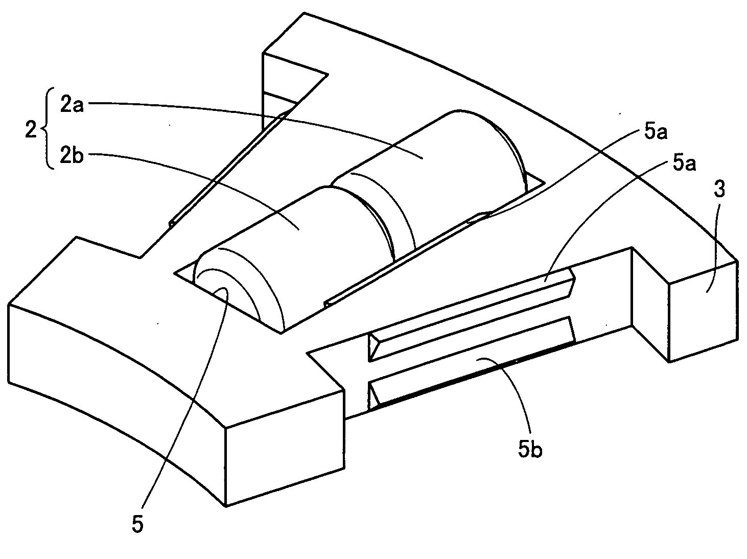
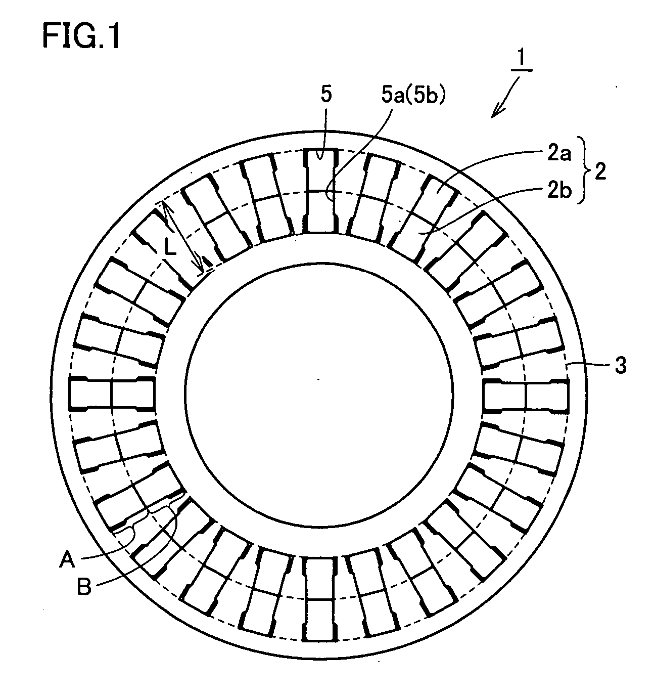
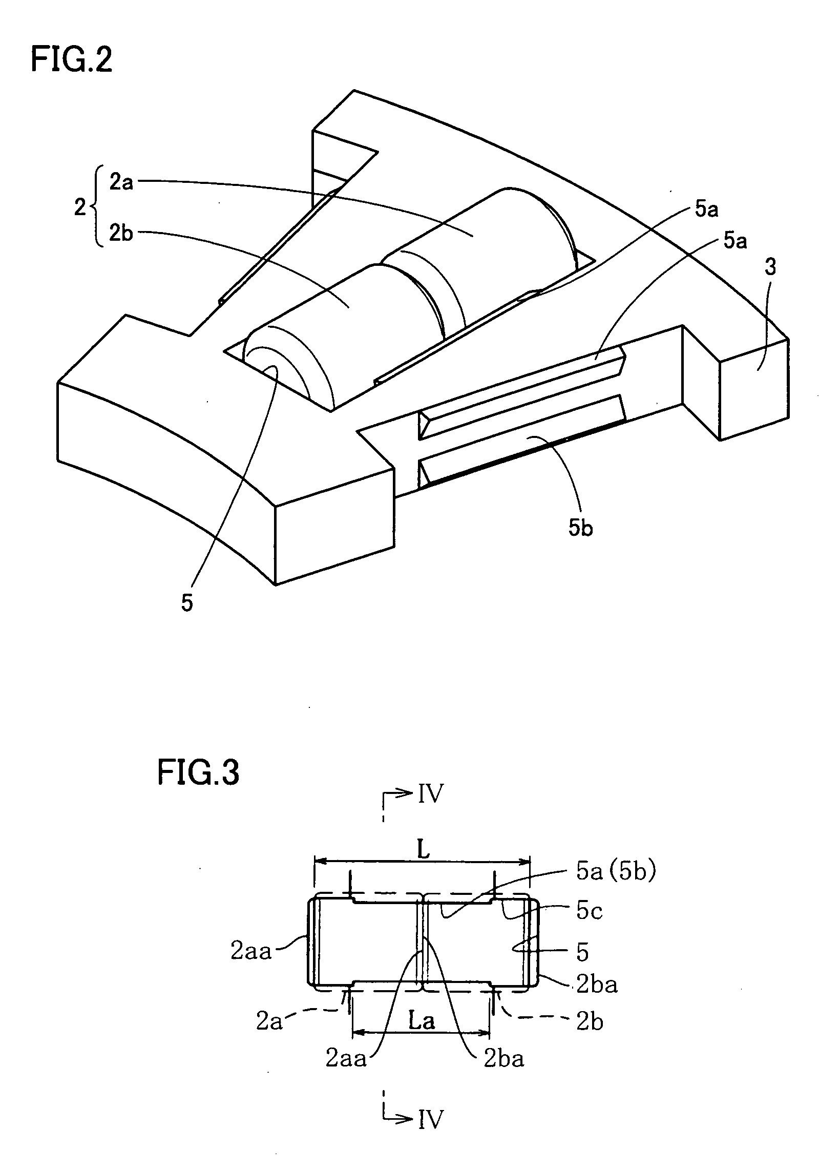
[0052] Referring to FIGS. 1 and 2, a thrust needle roller bearing 1 is formed of a plurality of needle rollers 2 and an annular retainer 3 retaining needle rollers 2 at positions spaced from each other with predetermined circumferential pitches. Retainer 3 has a plurality of rectangular pockets 5 each having a length longer than a radial length L (i.e., length in the radial direction of bearing 2) of needle roller 2. On each of opposite side edges of each packet 5, roller retaining portions 5a and 5b are formed and projected toward the other sides, respectively. These roller retaining portions 5a and 5b retain needle roller 2.

[0053] Referring to FIGS. 1 to 4, the plurality of needle rollers 2 are accommodated in the plurality of pockets 5, and are arranged in multiple (two) rows. Each pocket 5 accommodates two needle rollers 2, which are aligned to each other in the radial direction of retainer 3. Among needle rollers 2 arranged in the two rows, needle rollers 2b in the row on the ...

second embodiment

[0073] Referring to FIG. 8, a thrust needle roller bearing 31 according to a second embodiment includes retainer 3 having the plurality of pockets 5 arranged in two rows. Each pocket 5 accommodates one needle roller 2. Thus, the plurality of needle rollers 2 are arranged in the plurality of pockets 5 in a one-to-one relationship, and are arranged in multiple (two) rows. Among the plurality of pockets 5 arranged in two rows, pockets 16 in the row on the radially inner side of retainer 3 (i.e., in the row within region B defined by dotted line in FIG. 8) accommodate respective needle rollers 2b, which are equally spaced from each other, and pockets 15 in the row on the radially outer side of retainer 3 (i.e., in the row within region A defined by dotted line in FIG. 8) accommodate respective needle rollers 2a, which are equally spaced from each other. Needle rollers 2a are equal in number to needle rollers 2b.

[0074] In this embodiment, pockets 15 and 16 are formed such that a center ...

third embodiment

[0077] In thrust needle roller bearing 31 of the second embodiment, pockets 15 and 16 are formed such that center line 20 of pocket 15 matches with center line 21 of pocket 16. However, the thrust needle roller bearing according to the invention may have another structure as shown in FIG. 9.

[0078]FIG. 9 shows center line 20 of one pocket 15a among the plurality of pockets 15. Pockets 16a and 16b located in the row on the radially inner side of retainer 3 are arranged on the circumferentially opposite sides of each pocket 15a. FIG. 9 also shows center lines 21a and 21b of two pockets 16a and 16b, which are closer to one pocket 15a than other pockets 16. In a thrust needle roller bearing 32 according to this embodiment, pockets 15 and 16 are formed such that center line 20 equally divides an angle θ1 defined between center lines 21a and 21b. In other words, pockets 15 and 16 are formed such that an angle θ2 defined between center lines 21a and 20 is equal to an angle θ3 defined betwe...


PUM


Abstract

A thrust needle roller bearing includes a plurality of needle rollers, and an annular retainer having a plurality of pockets for retaining the needle rollers. The plurality of pockets accommodate the needle rollers arranged in multiple rows shifted from each other in a radial direction of the retainer, and the retainer is made of synthetic resin. The thrust needle roller bearing is light, can reduce friction between the retainer and the needle rollers, and has high durability.

Description

BACKGROUND OF THE INVENTION [0001] 1. Field of the Invention [0002] The present invention relates to a thrust needle roller bearing for use in a compressor of an air conditioner of an automobile. [0003] 2. Description of the Background Art [0004] A thrust needle roller bearing is formed of needle rollers, a retainer and a bearing washer, and the needle rollers make line-contact with the bearing washer so that it can achieve a high load capacity and a high rigidity although a bearing projection area is small. Therefore, the thrust needle roller bearings have been widely used as structures for bearing thrust loads in compressors of air conditioners of automobiles. Conditions of use are becoming more severe due to driving with lean lubrication or high-speed rotation. [0005] For example, Japanese Patent Laying-Open No. 2002-70872 has disclosed a conventional thrust needle roller bearing, in which inflow and / or outflow properties of lubricant or lubricating oil are improved for increasin...

Claims


Application Information

Patent Timeline
Patent Type & Authority Applications(United States)
IPC IPC(8): F16C19/30F16C19/32F16C33/46F16C19/44F16C33/48F16C33/52F16C33/56F16C33/58
CPCF16C19/30F16C33/4635F16C33/4676F16C33/56F16C2240/30F16C33/48
Inventor OBAYASHI, KOUSUKE
Owner NTN CORP
Why Eureka
Try Eureka