Opto-electric module and method of assembling

a technology of opto-electric modules and modules, applied in the field of opto-electric modules, can solve the problems of compromising electrical performance, affecting the electrical circuit impedance, and introducing mechanical stresses between the osas, so as to achieve the effect of maintaining the electrical and structural integrity of the modul

Inactive Publication Date: 2005-01-27
TE CONNECTIVITY CORP
View PDF4 Cites 29 Cited by
  • Summary
  • Abstract
  • Description
  • Claims
  • Application Information

AI Technical Summary

Benefits of technology

[0007] The present invention provides for a method of assembling an opto-electric module which avoids mechanically stressing the electrical interconnections between the various components by placing and aligning the various components in the opto-electrical module prior to effecting ...

Problems solved by technology

Although this prior art assembly approach meets the requirements of aligning and electrically connecting the various components, applicants have discovered that this approach introduces mechanical stresses between the OSAs and the circuit board during their installation into the module housing.
These stresses present a number of problems.
First, given the delicate nature of the components, any relative movement between them will necessarily introduce stresses in their electrical interconnections which may compromise electrical performance.
For example, stres...

Method used


Image

  • Opto-electric module and method of assembling
  • Opto-electric module and method of assembling
  • Opto-electric module and method of assembling

Examples


Embodiment Construction

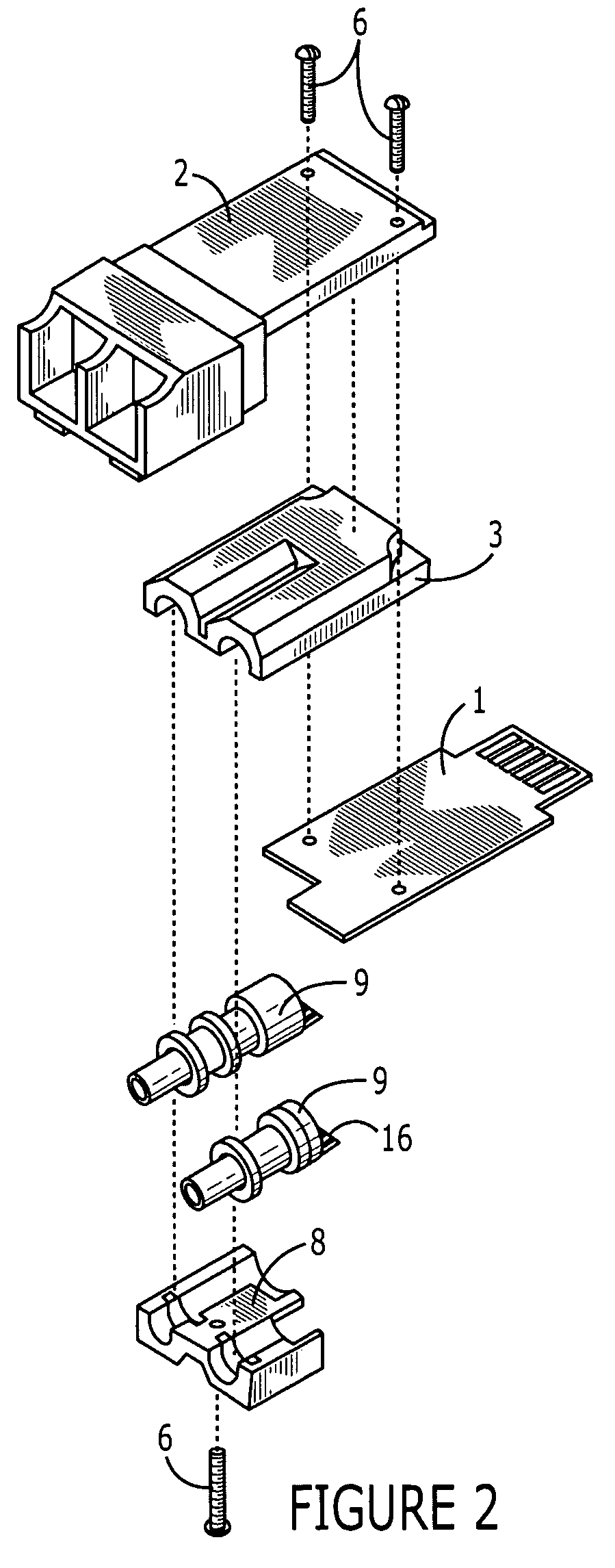
[0028] The invention herein described is a method of assembling the components of an opto-electric module wherein the step of electrically coupling the components is deferred until the components are spatially disposed and the opto-electric module assembled by such method. Deferring the step of electrically coupling the individual components of the module until the components are assembled reduces the potential of mechanical stress occurring at the electrical connections of the module and on the hermetic seal protecting the interior elements of the OSA.

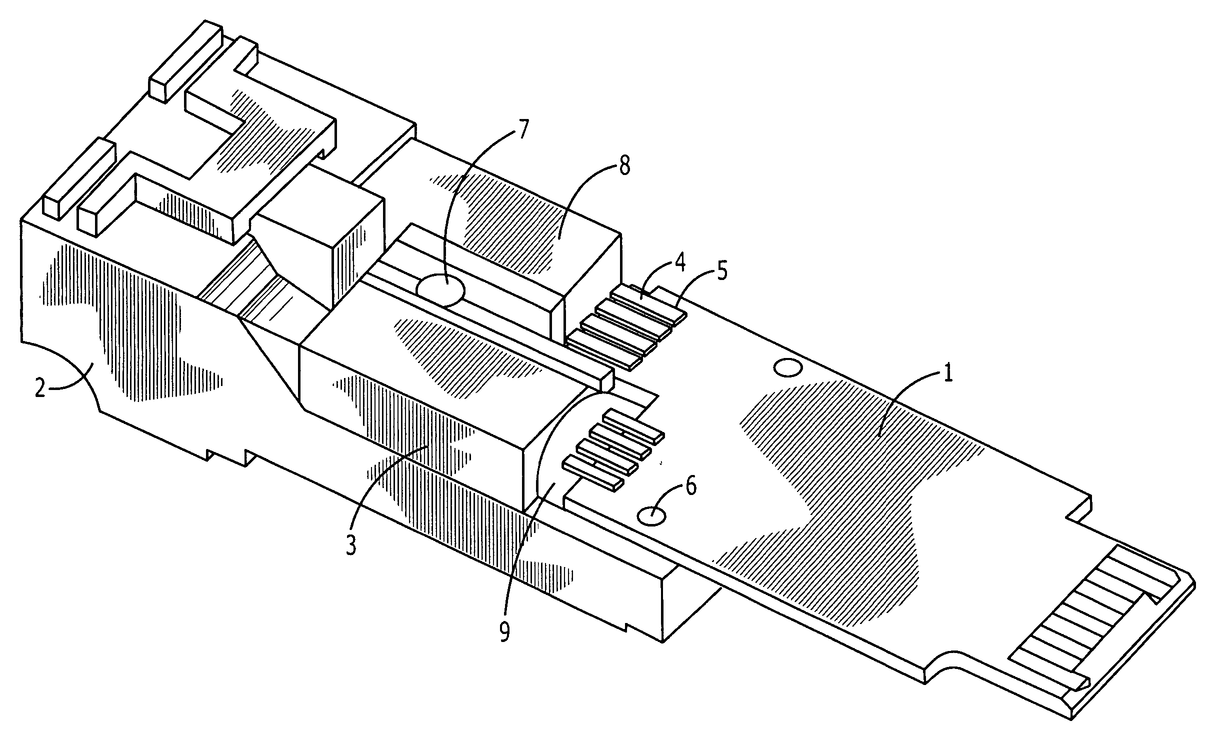
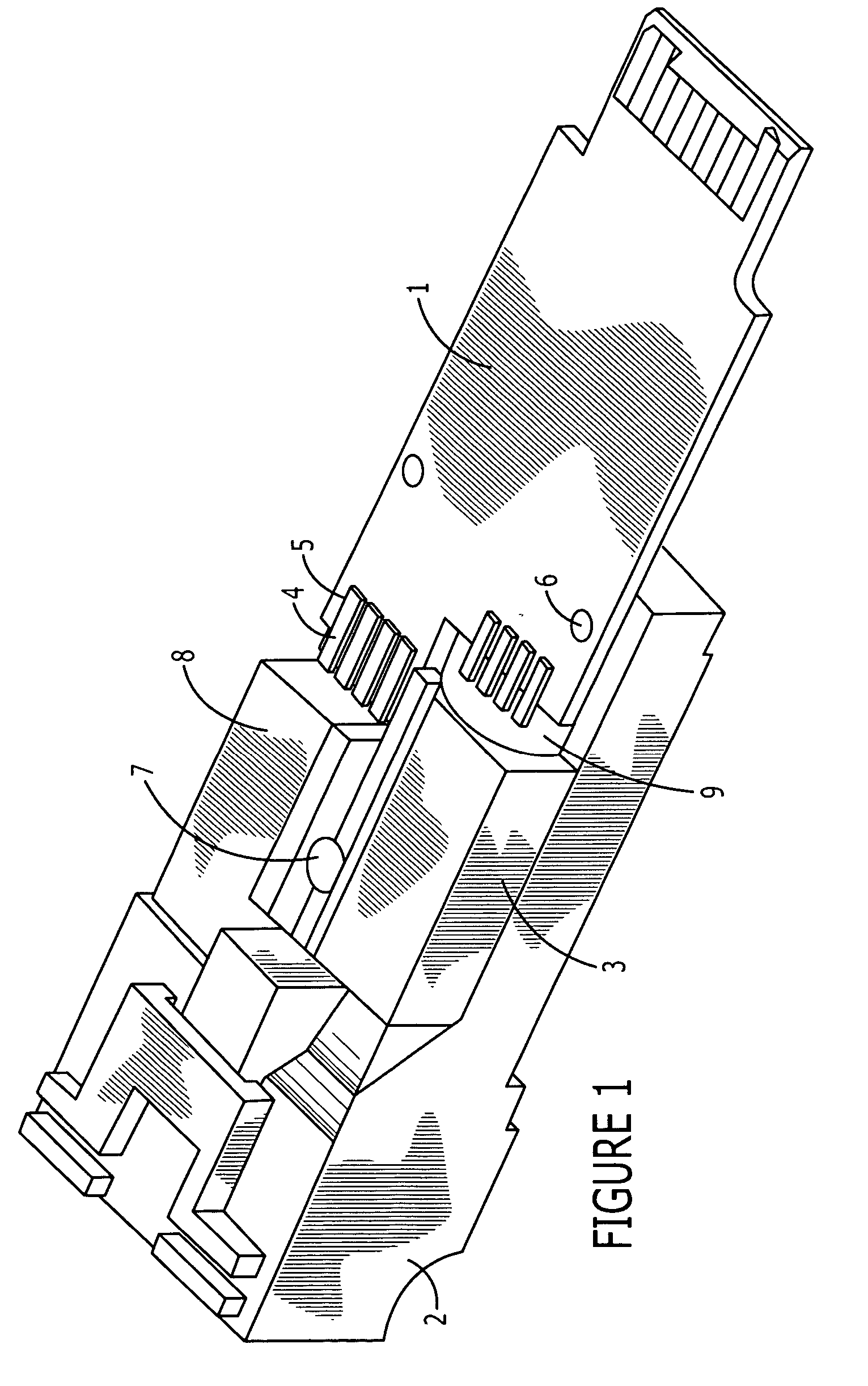
[0029] Referring to FIG. 1, an assembled opto-electric module is shown. This opto-electric module is designed to be part of an fiber optic communication system wherein the module receives an optical signal from an optical component, converts the optical signal to an electronic signal, optionally conditions the electronic signal, and then transmits the electronic signal to an electronic component (not shown). Alternatively, the module...


PUM


Abstract

An opto-electric module comprising: (a) an OSA having an optical axis, and optical end, an electrical end; (b) a planar circuit board having top and bottom surfaces and one or more electrical contacts on at least one of the surfaces of the circuit board; (c) a connector interface for receiving a mating connector; (d) a substrate connected to the connector interface, the OSA and the circuit board, the substrate holding the circuit board parallel to the optical axis of the OSA; and (e) an electrical interface between the electrical end of the OSA and the electrical contacts of the circuit board, the electrical interface comprising a flexible conductor extending orthogonally from the optical axis of the OSA and bending around to overlay the electrical contacts on the circuit board.

Description

REFERENCE TO RELATED APPLICATIONS [0001] This application claims priority to U.S. patent application Ser. No. 10 / 036,970 filed on Dec. 21, 2001, and to U.S. Provisional Application No. 60 / 516,675 filed on Nov. 3, 2003, both of which are hereby incorporated by reference.FIELD OF INVENTION [0002] The present invention relates generally to an opto-electrical module and a method of assembling it, and, more specifically, to an opto-electric module which is configured to be assembled to reduce stress on the electrical interconnections among the various components in the module. BACKGROUND [0003] An opto-electric transceiver module converts signals between the electrical and optical domains to transfer data between electrical circuitry and optical fiber. To perform this function, an opto-electric transceiver typically comprises a number of small, discrete components that are precisely aligned and electrically interconnected within the module. These components include, for example, a number...

Claims


Application Information

Patent Timeline
IPC IPC(8): G02B6/38G02B6/42
CPCG02B6/3849G02B6/4246G02B2006/4297G02B6/4292G02B6/4277
Inventor NEVO, RONCANACE, DOMINICSCHNOOR, WILLIAM JOHN
Owner TE CONNECTIVITY CORP
Why Eureka
Try Eureka