Single-fiber protection in telecommunications networks

a technology of single fiber and telecommunications network, applied in multiplex communication, transmission monitoring, instruments, etc., can solve the problems of inability to support extra traffic, inconvenient operation, and inability to support traffi

Active Publication Date: 2005-01-27
SCHOFIELD TECH
View PDF16 Cites 69 Cited by
  • Summary
  • Abstract
  • Description
  • Claims
  • Application Information

AI Technical Summary

Benefits of technology

[0077] Lastly, according to the various aspects of the invention, optical power otherwise lost because of ring protection by using 2-by-2 and 2-by-n splitters may be saved.

Problems solved by technology

A single link failure may result in an intolerable traffic loss, which indirectly leads to revenue loss.
However, in this architecture, no extra traffic can be supported.
One problem in prior-art solutions and also in the solution disclosed in FIG. 1, is that an optical signal traversing through ring splitters / combiners 10 and 11 experience optical power losses at two different stages (ring splitters / combiners 10 and 11).
The prior-art passive optical networks involve further problems that have to be overcome.
In an access network, the cost is a major concern since the number of users in the access network is much less than that in metro or backbone networks.
Furthermore, there exists a problem of how to effectively provide protection against a single link failure in a PON based access network without significantly increasing the cost per user.
A further problem is how to implement fast fault detection in a PON.
Yet a further problem is how to fast reroute the affected traffic from the working OLT to the protection OLT.
A further problem is how to solve the attenuation problem caused by protection elements.

Method used


Image

  • Single-fiber protection in telecommunications networks
  • Single-fiber protection in telecommunications networks
  • Single-fiber protection in telecommunications networks

Examples


Embodiment Construction

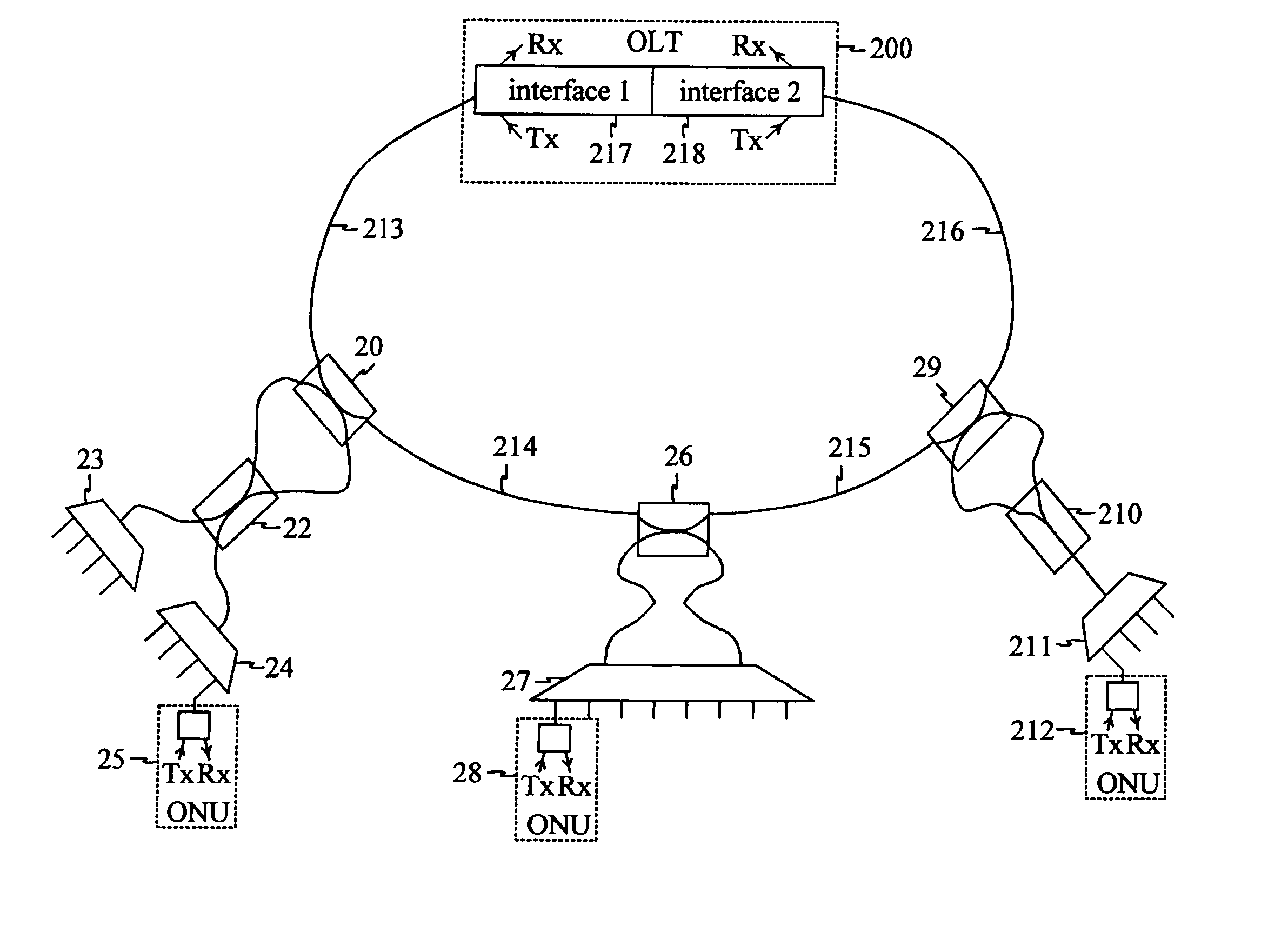
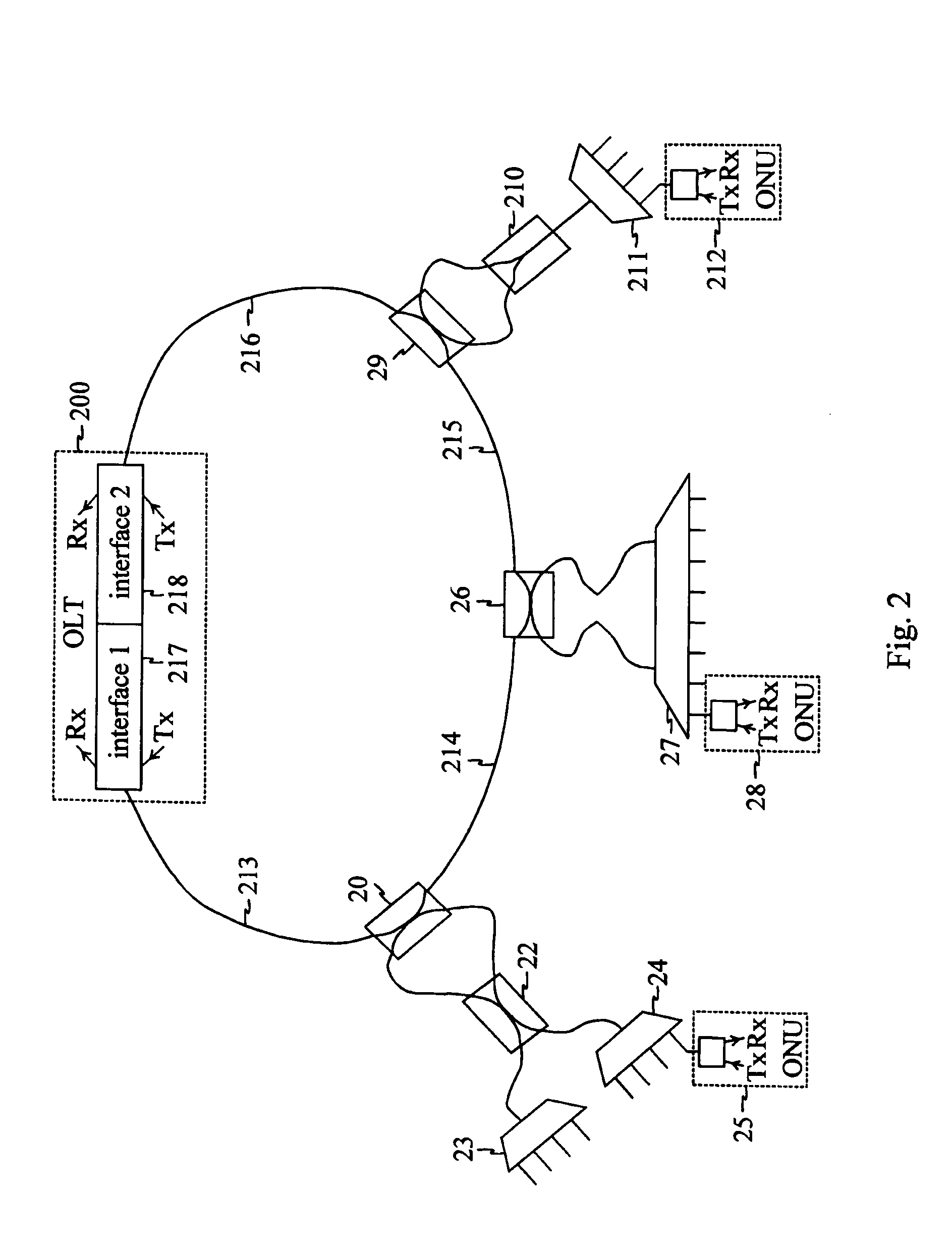
[0094]FIG. 2 describes a ring-protected PON arrangement configured to serve a number of subscribers. This arrangement includes an OLT 200 having two interfaces 217 and 218, each having a transceiver. Interface 217 is an active interface whereas interface 218 is a standby interface. The distribution network in this example includes three 2-by-2 ring splitters / combiners 20, 26, 29 connected by fiber distribution lines 213-216 to form a ring between the two interfaces 217 and 218. Each ring splitter / combiner 20, 26, 29 is linked to a number of subscriber ONUs 25, 28, 212 via intermediate splitters / combiners 22, 23, 24, 27, 210, 211. The transmitters of OLT 200 are configured to transmit optical signals on a first wavelength (for example 1490 nm). Correspondingly, the receiver of OLT 200 is configured to receive optical signals on a second wavelength (for example 1310 nm). In order to avoid interference, the transmitter of ONUs 25, 28, 212 are configured to transmit optical signals on t...


PUM


Abstract

A solution for detecting and recovering from a failure in a protected single-fiber passive optical network. A detector is used to detect the degradation in power level of optical signals. Furthermore, the invention discloses a variable symmetric split ratio approach to improve the number of splits (e.g. the number of ONUs). A single-fiber passive optical network is disclosed that uses a plurality of passive nodes connected in the optical fiber between the interfaces, wherein in the passive nodes 2-by-2 splitters/combiners are used to couple optical power from and into the optical fiber at a predetermined split ratio.

Description

BACKGROUND OF THE INVENTION [0001] 1. Field of the Invention [0002] The invention relates to passive optical networks, and in particular to protected passive optical networks. [0003] 2. Description of the Related Art [0004] A Passive Optical Network (PON) is a high bandwidth point-to-multipoint optical fiber network. A PON typically consists of an Optical Line Terminal (OLT), which is connected to Optical Network Units (ONU) using only cables, optical splitters and other passive components (i.e. not transmitting signals using electricity). In a PON, signals are routed in such a way that all signals reach all interim transfer points of the PON. [0005] Passive optical network technology has been considered a very promising solution for solving the last-mile problem. Logically a PON has a tree-like structure consisting of an optical line terminal, which is located e.g. in a central office (CO), and a plurality of optical network units, e.g. 64 ONUs. The PON technology eliminates the ne...

Claims


Application Information

Patent Timeline
Patent Type & Authority Applications(United States)
IPC IPC(8): H04BH04B10/077H04B10/079H04B10/27H04B10/275H04J3/16
CPCH04B10/077H04B10/275H04B10/27H04B10/07955H04B10/032H04B10/25H04J3/16
Inventor YE, YINGHUAPIETILAINEN, ANTTI
Owner SCHOFIELD TECH
Why Eureka
Try Eureka