Hybrid fuel cell-pulse detonation power system

a fuel cell and power system technology, applied in the direction of machines/engines, intermittent jet plants, lighting and heating apparatus, etc., can solve the problems of large fuel cells that are difficult to fabricate, large number of complex rotating machinery, and long time scale to reach full load

Inactive Publication Date: 2005-01-27
GENERAL ELECTRIC CO
View PDF5 Cites 27 Cited by
  • Summary
  • Abstract
  • Description
  • Claims
  • Application Information

AI Technical Summary

Problems solved by technology

One challenge facing fuel cell power generation is the long time scale to get to full load.
Large fuel cells can be expensive and difficult to fabricate.
However, these systems involve numerous pieces of complex rotating machinery.

Method used


Image

  • Hybrid fuel cell-pulse detonation power system
  • Hybrid fuel cell-pulse detonation power system
  • Hybrid fuel cell-pulse detonation power system

Examples


Embodiment Construction

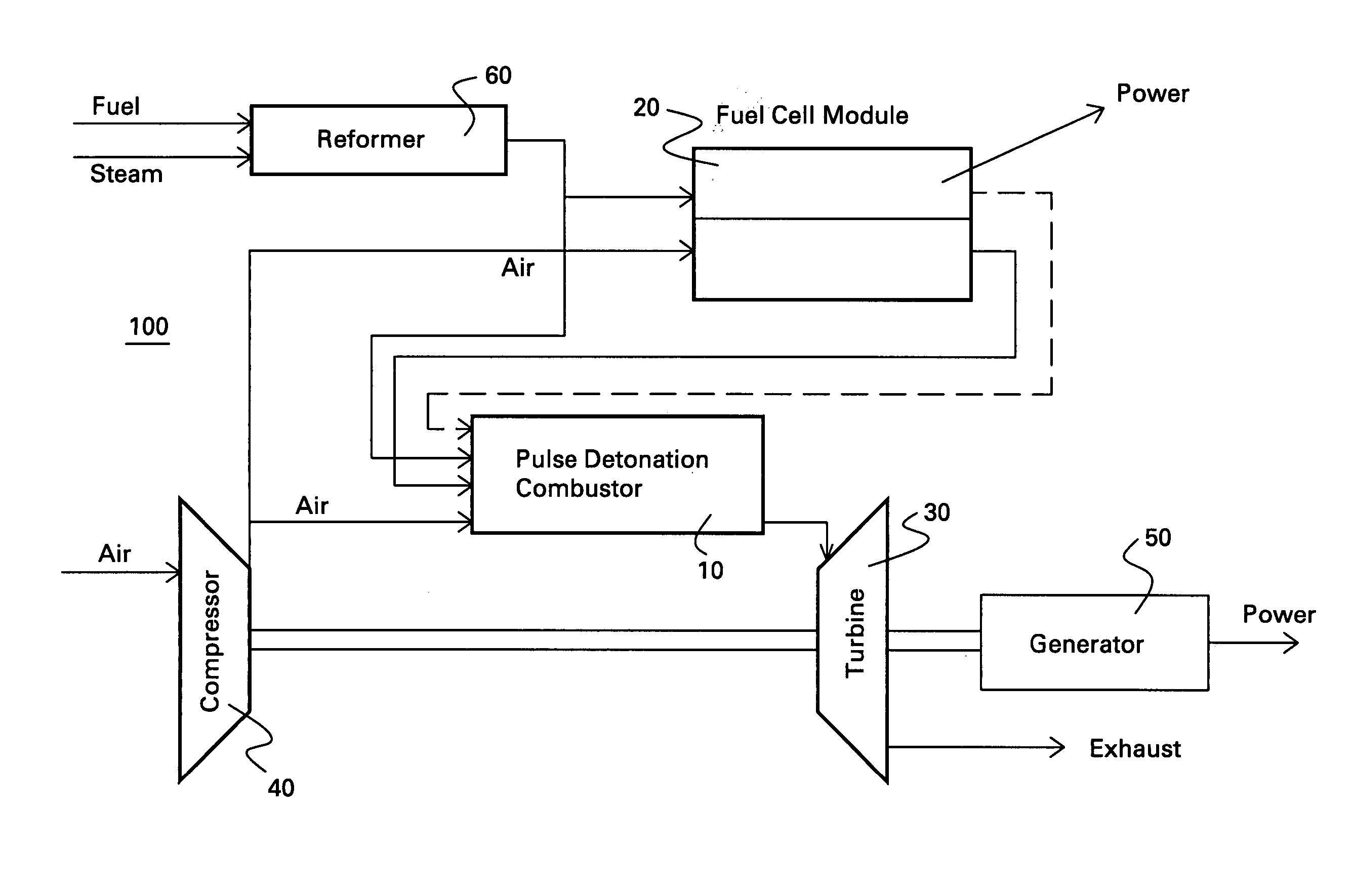
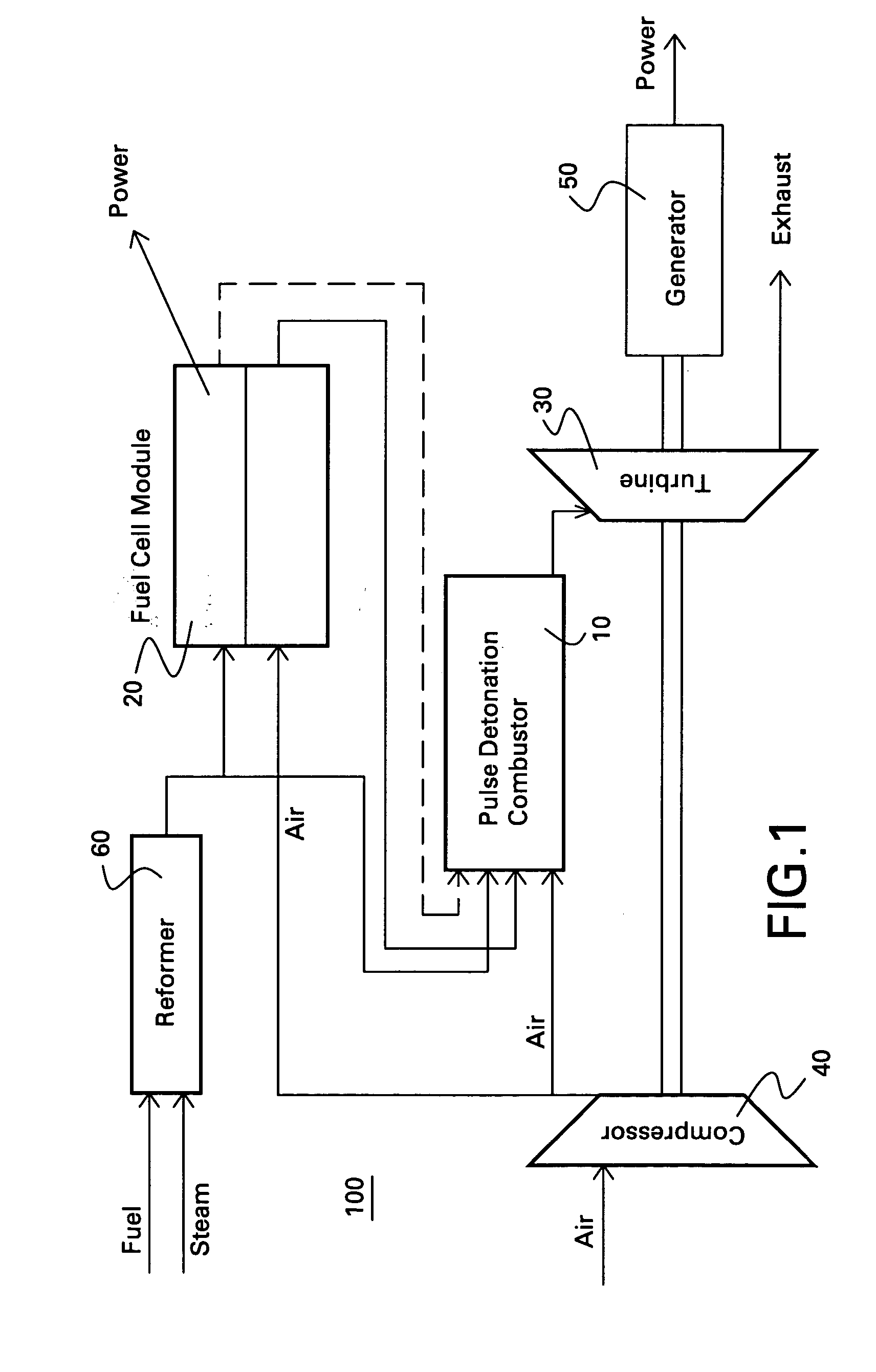
[0013] A power system 100 is described with reference to FIG. 1. As shown in FIG. 1, the power system 100 includes a fuel cell module 20 adapted to receive a first fuel, and a pulse detonation combustor 10 adapted to receive and detonate a second fuel and exhaust a number of detonation products to create thrust for propulsion, mechanical work extraction or electrical power production.

[0014] Exemplary pulse detonation combustors 10 have a number of pulse detonation chambers 16, as indicated in FIG. 3, for example.

[0015] As used herein, a “pulse detonation combustor” is understood to mean any device or system that produces both a pressure rise and velocity increase from a series of repeating detonations or quasi-detonations within the device. A “quasi-detonation” is a supersonic turbulent combustion process that produces a pressure rise and velocity increase higher than the pressure rise and velocity increase produced by a deflagration (or constant-pressure combustion) wave. Typical...


PUM

PropertyMeasurementUnit
temperatureaaaaaaaaaa
poweraaaaaaaaaa
electric poweraaaaaaaaaa

Abstract

A power system includes a fuel cell module adapted to receive a first fuel and a pulse detonation combustor adapted to receive and detonate a second fuel and exhaust a number of detonation products to create thrust for propulsion, mechanical work extraction or electrical power production.

Description

BACKGROUND OF THE INVENTION [0001] The invention relates generally to hybrid cycle power generation and, more particularly, to a hybrid fuel cell / pulse detonation engine power system. [0002] Fuel cells, for example solid oxide fuel cells (SOFCs), are energy conversion devices that produce electricity by electrochemically combining a fuel and an oxidant across an ion conducting layer. For power generation applications, large numbers of fuel cells arranged in stacks are used to generate electric power. [0003] One challenge facing fuel cell power generation is the long time scale to get to full load. Although the time constants vary by fuel cell type, they typically range from a few hours to days for powers of about a megawatt or more. In contrast, conventional one-hundred watt (100 MW) gas turbines go from cold start to full load in less than about five (5) minutes. Accordingly, it would be desirable to have a rapid start option for power systems that incorporate fuel cells. [0004] An...

Claims


Application Information

Patent Timeline
Patent Type & Authority Applications(United States)
IPC IPC(8): F01K23/10F02C3/20F02C3/28F02C5/00F02C6/00F02C6/18F02C7/22F02K7/02F02K7/06F23R7/00H01M8/00H01M8/04H01M8/06H01M8/12
CPCF02C3/20F02C3/28F02C5/00F02C6/18F02K7/02Y02E20/16H01M8/04022H01M8/04089H01M8/0612Y02E60/50F02K7/06
Inventor SCHICK, LOUIS ANDREWDEAN, ANTHONY JOHN
Owner GENERAL ELECTRIC CO
Why Eureka
Try Eureka