Fuel cell cogeneration system

a cogeneration system and fuel cell technology, applied in domestic hot water supply systems, heating types, sustainable manufacturing/processing, etc., can solve the problems of shortening the hot water storage means, consumers are incapable of consuming hot water, and hot water may run out with use, so as to inhibit hot water from running out and improve convenience.

Inactive Publication Date: 2005-01-27
PANASONIC CORP
View PDF2 Cites 25 Cited by
  • Summary
  • Abstract
  • Description
  • Claims
  • Application Information

AI Technical Summary

Benefits of technology

[0008] The present invention has been directed to solving the above described problem, and an object of the present invention is to provide a fuel cell cogeneration system capable of inhibiting hot water from running out and of improving convenience.

Problems solved by technology

However, since consumers typically consume hot water regardless of the amount of hot water remaining within the heat utilization means, the hot water may run out with use when the hot water stored in the heat utilization means is running short.
Especially when the heat utilization means is not internally equipped with a backup hot water supply device for ensuring the hot water, consumers are incapable of consuming the hot water.
This presents a serious inconvenience.

Method used


Image

  • Fuel cell cogeneration system
  • Fuel cell cogeneration system
  • Fuel cell cogeneration system

Examples


embodiment 1

[0043] (Embodiment 1)

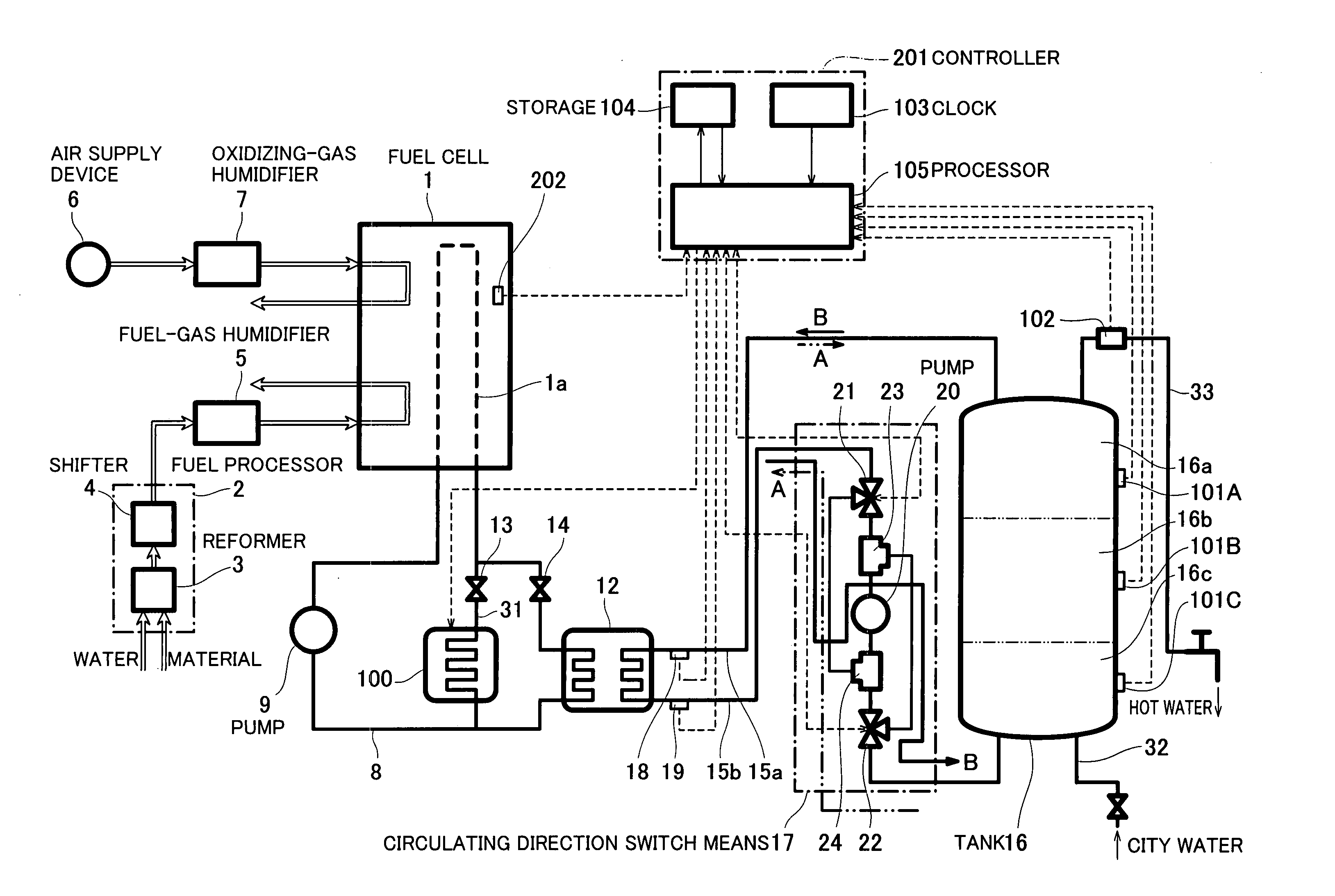
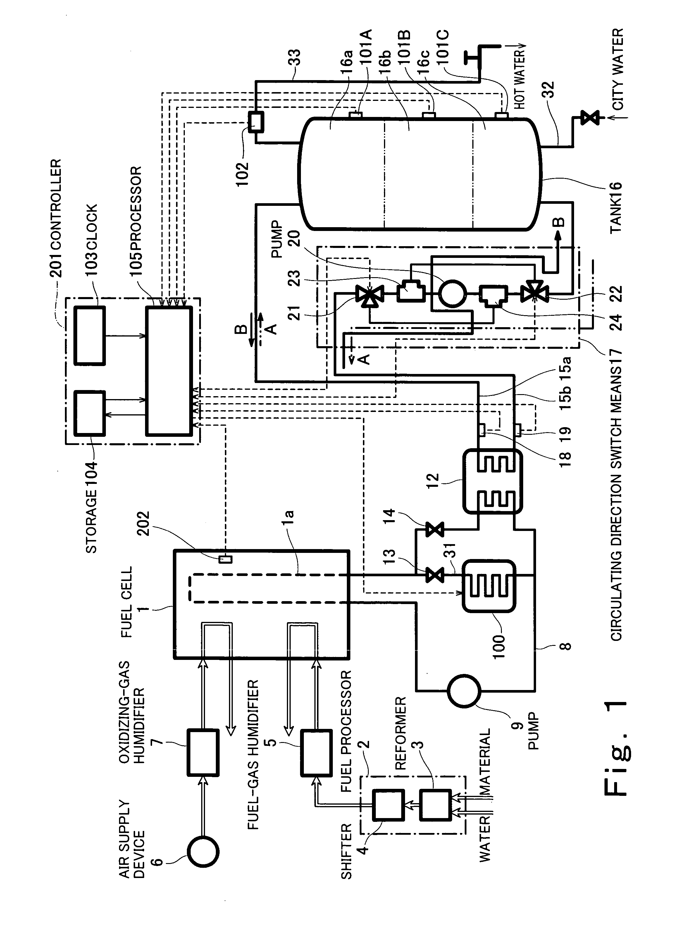
[0044]FIG. 1 is a block diagram showing a construction of a fuel cell cogeneration system according to a first embodiment of the present invention.

[0045] Turning to FIG. 1, the fuel cell cogeneration system (hereinafter simply referred to as cogeneration system) is chiefly divided into a construction of hardware and a configuration of a control system.

[0046] First of all, the construction of the hardware will be described. The cogeneration system comprises a fuel cell 1 configured to generate an electric power using a fuel gas and an oxidizing gas, a fuel processor 2 configured to generate a fuel gas from a material and water and to supply the fuel gas to the fuel cell 1, a fuel-gas humidifier 5 configured, to humidify the fuel gas being supplied to the fuel cell 1 at a position in a flow path extending to the fuel cell 1, an air supply device 6 configured to supply air as an oxidizing gas to the fuel cell 1, and an oxidizing-gas humidifier 7 configured to hum...

embodiment 2

[0103] (Embodiment 2)

[0104] Although the temperature increasing means select threshold QLT is set considering the life pattern of consumers in the alternative examples 2 and 3 of the first embodiment, the life pattern of the consumers varies depending on seasonal change. In general, the calories used for hot water supply or air conditioning in the morning tend to increase as ambient air temperature decreases. In the second embodiment, the threshold OLT is set considering the variation in the consumed calories during the start time period due to such seasonal change.

[0105]FIG. 8 is a block diagram showing a construction of a fuel cell cogeneration system according to the second embodiment of the present invention. In FIG. 8, the same reference numerals as those in FIG. 1 denote the same or corresponding parts which will not be further described.

[0106] In the second embodiment, an ambient air temperature sensor 106 is attached at a proper position to detect ambient air temperature. ...

example 1

[0119] [Alternative Example 1 of the Embodiment 2]

[0120] An alternative example 1 of the second embodiment will now be described.

[0121] In the alternative example 1, the ambient air temperature sensor 106 configured to detect the ambient air temperature, which is shown in FIG. 8, is omitted. And, the processor 105 calculates monthly average start time period consumed calories and selects temperature increasing means based on the monthly average start time period consumed calories. This follows that the temperature increasing means is selected considering the ambient air temperature. The other construction is identical to that in FIGS. 8 and 9.

[0122] Hereinafter, the difference between the construction of the alternative example 1 and the construction in FIGS. 8 and 9 will be described.

[0123]FIG. 11 is a flowchart showing an operation to select a temperature increasing means of a fuel cell cogeneration system according to the alternative example 1 of the second embodiment. FIG. 12...


PUM

PropertyMeasurementUnit
timeaaaaaaaaaa
heataaaaaaaaaa
heat utilizationaaaaaaaaaa

Abstract

A fuel cell cogeneration system comprises a fuel cell, a cooling system for the fuel cell, a heater, a heat utilization portion configured to store heat recovered in the cooling system to allow the heat to be consumed, a detector configured to detect calories remaining in the heat utilization portion, and a controller, wherein the controller determines whether or not the calories remaining in the heat utilization portion are at least not less than the calories required to increase the temperature of the fuel cell to the operating temperature, and based on determination, increases the temperature of the fuel cell to the operating temperature by supplying the remaining calories to the fuel cell through the cooling system and/or by heating the cooling water in the cooling system by the heater.

Description

BACKGROUND OF THE INVENTION [0001] 1. Field of the Invention [0002] The present invention relates to a fuel cell cogeneration system. [0003] 2. Description of the Related Art [0004]FIG. 16 is a block diagram showing a construction of the conventional fuel cell cogeneration system (see Japanese Laid-Open Patent Application Publication No. 2002-042841, page 3 to 6, FIG. 1). [0005] Turning to FIG. 16, the fuel cell cogeneration system comprises a fuel cell 1 configured to generate an electric power using a fuel gas and an oxidizing gas, a fuel processor 2 configured to generate the fuel gas by subjecting a material to a steam reforming reaction and a shift reaction, a fuel-gas humidifier 5 configured to humidify the fuel gas to be supplied to the fuel cell 1, an air supply device 6 configured to supply air as the oxidizing gas to the fuel cell 1, and an oxidizing-gas humidifier 7 configured to humidify the air. [0006] The fuel cell cogeneration system further comprises a cooling pipe 8...

Claims


Application Information

Patent Timeline
Patent Type & Authority Applications(United States)
IPC IPC(8): H01M8/00H01M8/02H01M8/04
CPCF24D17/001F24D2240/26F24D2200/19H01M8/04029H01M8/04037H01M8/04052H01M8/04059H01M8/04358H01M8/04373H01M8/04425H01M8/04723H01M8/04738H01M8/04955H01M2250/405Y02E60/50Y02B90/16F24D2220/042F24D19/1051Y02P80/15Y02B30/18Y02B90/10
Inventor MIYAUCHI, SHINJIUEDA, TETSUYAYAMAMOTO, YOSHIAKI
Owner PANASONIC CORP
Why Eureka
Try Eureka