Battery provided with terminals

Active Publication Date: 2005-01-27
MAXELL HLDG LTD
View PDF2 Cites 35 Cited by
  • Summary
  • Abstract
  • Description
  • Claims
  • Application Information

AI Technical Summary

Benefits of technology

[0011] It is a first object of the present invention to provide a battery provided with terminals, which is capable of solving the problems th

Problems solved by technology

However, since the battery may be subjected to a high temperature, for example, over 150° C. when the battery is passed through the reflow soldering furnace and heated, even for a short time, a physical change or chemical change occurs in the structure members of the battery, resulting in deterioration of the sealing characteristic, the discharge characteristic, and the cycle characteristic of the battery, which causes a short circuit in the battery.
On the other hand, manual soldering application to the batteries, excluding other electronic parts in order to protect the battery, causes significant deterioration of work efficiency.
However, it has been proven that to make the battery heat resistant causes the following problems.
That is, in the former two cases where the packing of the battery is made of a heat resistant material in order to prevent the battery from being damaged when passing through the reflow furnace, the cost of the material significantly increases compar

Method used


Image

  • Battery provided with terminals
  • Battery provided with terminals
  • Battery provided with terminals

Examples


Example

[0030] (First Embodiment)

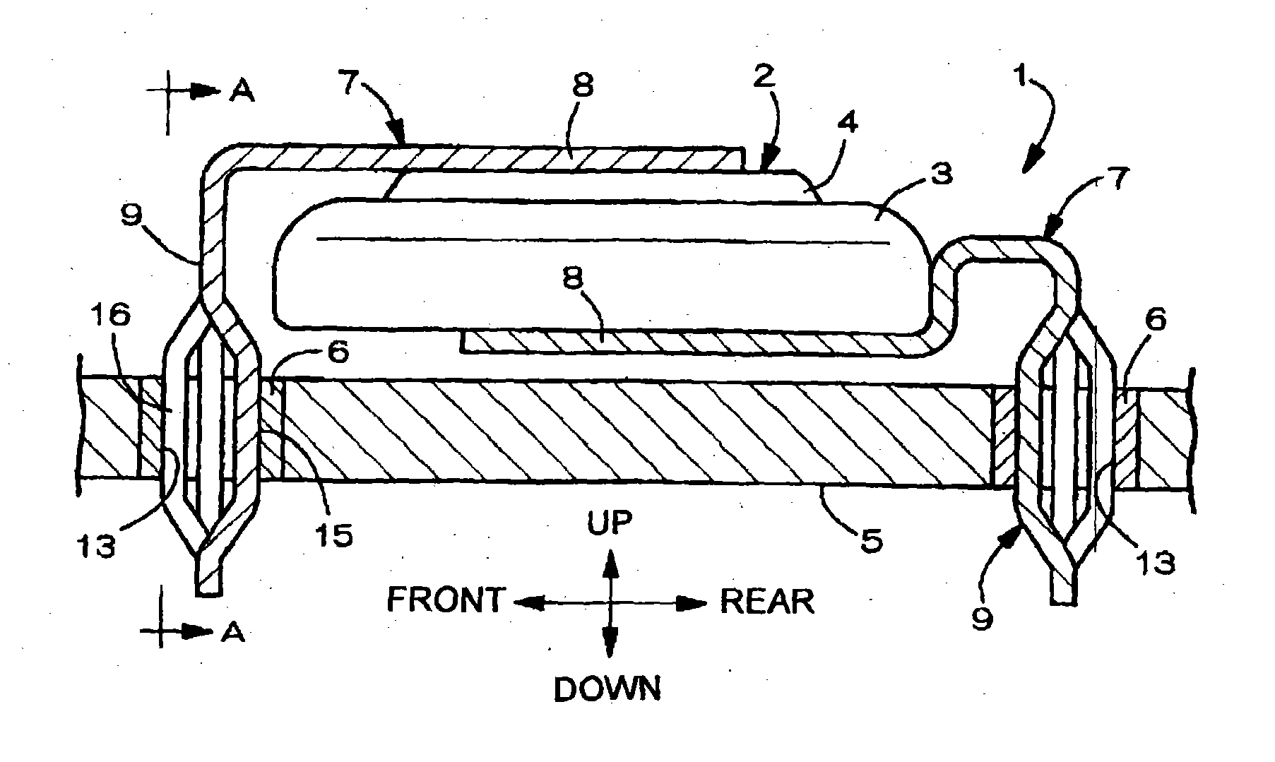
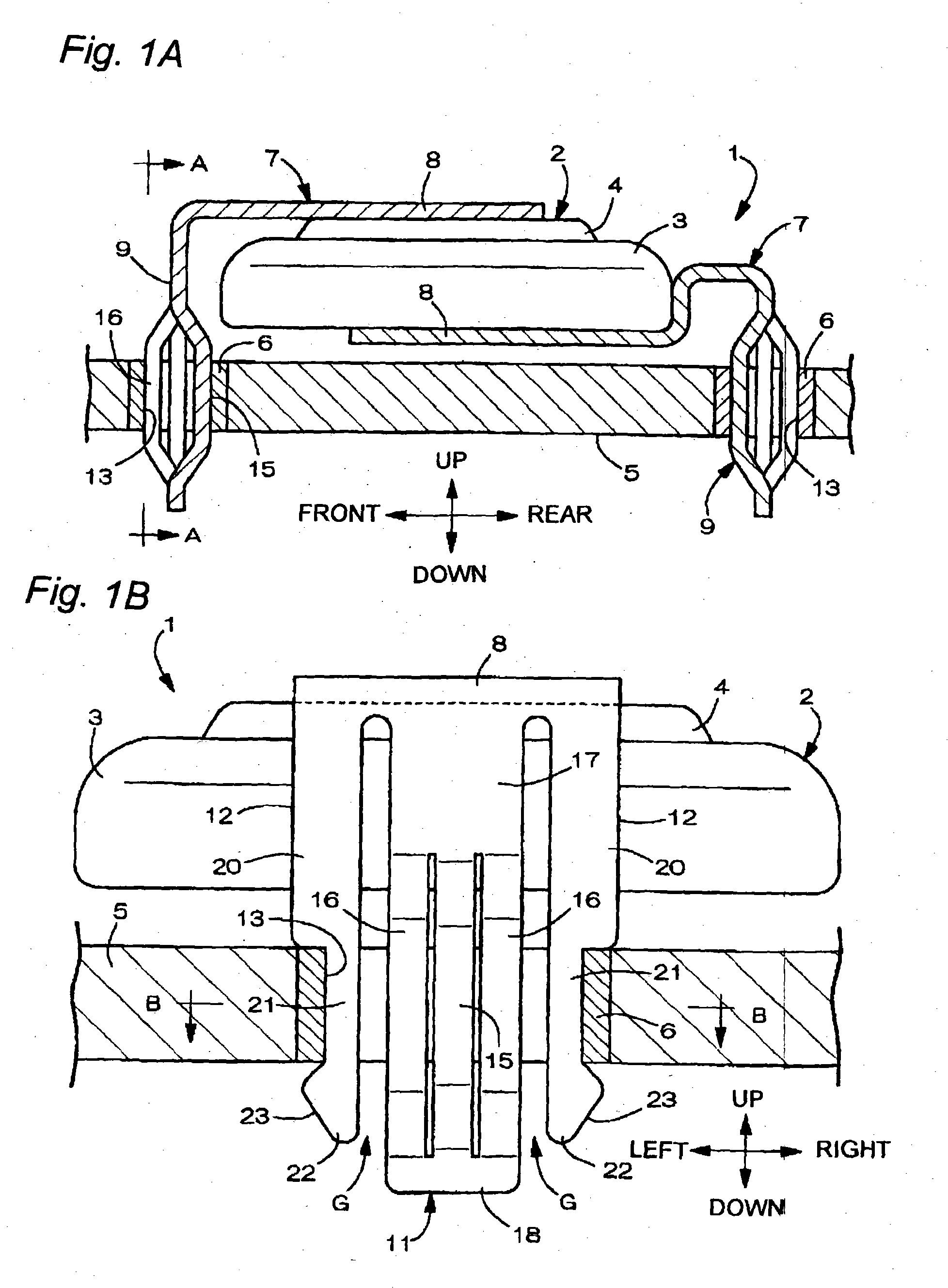
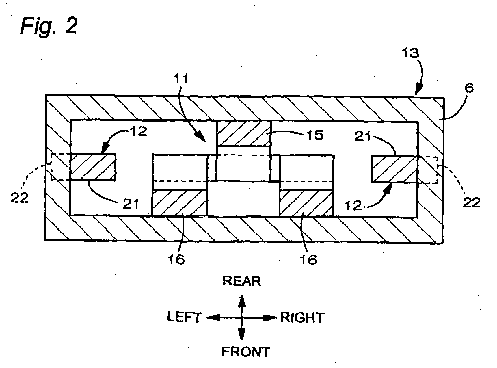
[0031] A battery provided with terminals according to the present invention will be described with a coin-shaped lithium battery taken as an example. FIG. 1A is a side view of a coin-shaped lithium battery 1. FIG. 1B is a front view of a terminal 7 in a negative electrode, which is taken along the line A-A in FIG. 1A. FIG. 2 is a sectional view, which is taken along the line B-B of FIG. 1B. The coin-shaped lithium battery 1 includes a battery body 2 and terminals 7 welded and fixed to the positive electrode and the negative electrode of the battery body 2. The battery body 2 includes a bottomed cylindrical battery case 3, which has an opening on an upper surface, and a cover 4 for sealing up the opening. The battery case 3 is the positive electrode, and the cover 4 is the negative electrode.

[0032] The terminals 7 electrically connect the conductive portions 6 provided in the circuit board 5 to the positive electrode and the negative electrode of the batter...

Example

[0042] (Second Embodiment)

[0043] A second embodiment of the battery provided with terminals, according to the present invention, is shown in FIGS. 3 and 4. In this case, the battery provided with terminals l includes the battery body 2, a negative electrode terminal 7a, that is welded and fixed to the upper surface of the battery body 2, and an positive electrode terminal 7b, that is welded and fixed to the lower surface of the battery body 2. The battery provided with terminals 1 is mounted in and fixed to the peripheral edge of the circuit board 5.

[0044] The negative electrode terminal 7a is a press metal fitting in which a horizontal arm 30, extending backward, is integrated with a contacting portion 31, which is formed by bending it in a V-shape in the free end of the horizontal arm 30, to contact the conductive portion 6a of the circuit board 5. The base end of the horizontal arm 30 is welded and fixed to the upper surface of the battery body 2. The contacting portion 31 with...

Example

[0049] (Third Embodiment)

[0050] A third embodiment of the battery provided with terminals according to the present invention is shown in FIGS. 5 and 6. The battery provided with terminals 1 includes the battery body 2, a negative electrode terminal 7a which is welded and fixed to the upper surface of the battery body 2, and a positive electrode terminal 7b which is welded and fixed to the lower surface of the battery body 2. The battery 1 is fixed to and mounted on the circuit board 5 using rivets 40.

[0051] The negative electrode terminal 7a is a press formed product obtained by bending a horizontal portion 41 which is extended outward from the battery body 2, and a backing plate (a contacting portion) 42, which is fixed to the circuit board 5 by rivet in the shape of steps. A through hole 43 for the rivet 40 is formed in the center of the backing plate 42. The positive electrode terminal 7b is a long flat metal plate, and a through hole 45 for the rivet 40 is provided in the cent...


PUM


Abstract

A battery provided with terminals, which is capable of being mounted on a circuit board without soldering, is disclosed. The battery includes a battery body 2, and terminals 7 for electrically connecting the battery body 2 to conductive portions 6 provided in a circuit board 5. A portion of each of the terminals 7 is a fixing portion 9 for fixing the battery body 2 to the circuit board 5.
The fixing portion 9 of each of the terminals 7 is provided with engaging portions 12, which penetratingly engage a portion where the conductive portion 6 is provided or a portion in the vicinity of the conductive portion 6, and a contacting portion 11, which contacts the conductive portion 6 to electrically connect the conductive portion 6 to the battery body 2, so that the battery body 2 is fixed in a state of being electrically connected to the conductive portions 6 of the circuit board 5.

Description

BACKGROUND OF THE INVENTION [0001] 1. Field of the Invention [0002] The present invention relates to a battery provided with terminals, and more particularly, to a battery provided with terminals, capable of being attached to a circuit board of an electronic apparatus without soldering. [0003] 2. Description of the Related Art [0004] In a flat battery such as button-shaped and coin-shaped batteries, or square and cylindrical batteries, a primary battery and a secondary battery represented by an alkaline dry battery, a lithium battery, a lithium secondary battery, and an alkaline storage battery are widely used as main power sources, or backup power supplies for memories of various electronic apparatuses. [0005] When mounting the battery on a circuit board of an electronic apparatus, it is suggested that terminals for soldering a battery to the circuit board, should be attached to the battery and that the battery is soldered to the circuit board together with other electronic parts b...

Claims


Application Information

Patent Timeline
IPC IPC(8): H01M50/559H01M50/541H01M50/562H01M50/566H05K1/18H05K3/30
CPCH01M2/0222H01M2/1044H01M2/30H05K2201/10856H05K3/308H05K2201/1059H05K1/182Y02E60/10H01M50/109H01M50/216Y02P70/50H01M50/566H01M50/562H01M50/559
Inventor KISHIDA, AKIRA
Owner MAXELL HLDG LTD
Why Eureka
Try Eureka