Lathe

a technology of lathes and workpieces, applied in the field of lathes, can solve the problems of reducing the accuracy of machining, and not always achieving high accuracy squareness between the sides of the rectangular shape, etc., and achieve the effect of high accuracy

Inactive Publication Date: 2005-02-03
DMG MORI SEIKI CO LTD
View PDF10 Cites 13 Cited by
  • Summary
  • Abstract
  • Description
  • Claims
  • Application Information

AI Technical Summary

Benefits of technology

[0033] With this configuration, the heat insulating materials prevent heat transfer from the housing to the support base, whereby any thermal displacement of the support base can be restraine

Problems solved by technology

As a result, an error occurs in the relative positional relationship between the workpiece held in the main spindle 103 and the tool T held in the first tool rest 110, and similarly an error occurs in the relative positional relationship between the workpiece held in the main spindle 106 and the tool T held in the second tool rest 115, whereby there is a problem of reducing the accuracy of machining.
However, conventionally, the accuracy of indexing the workpiece W is not always sufficiently high.
Hence, the above-mentioned method has a

Method used


Image

  • Lathe
  • Lathe
  • Lathe

Examples


Embodiment Construction

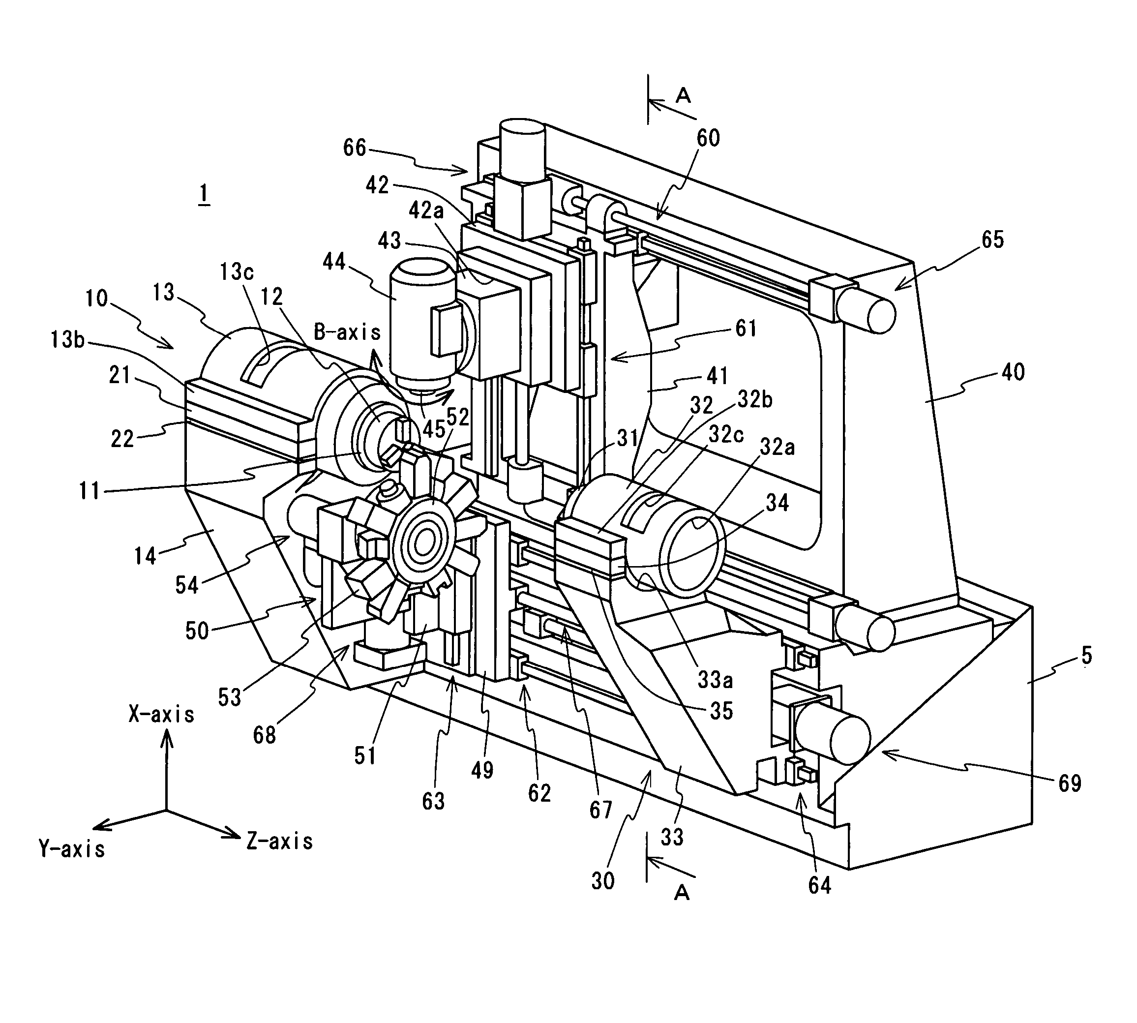
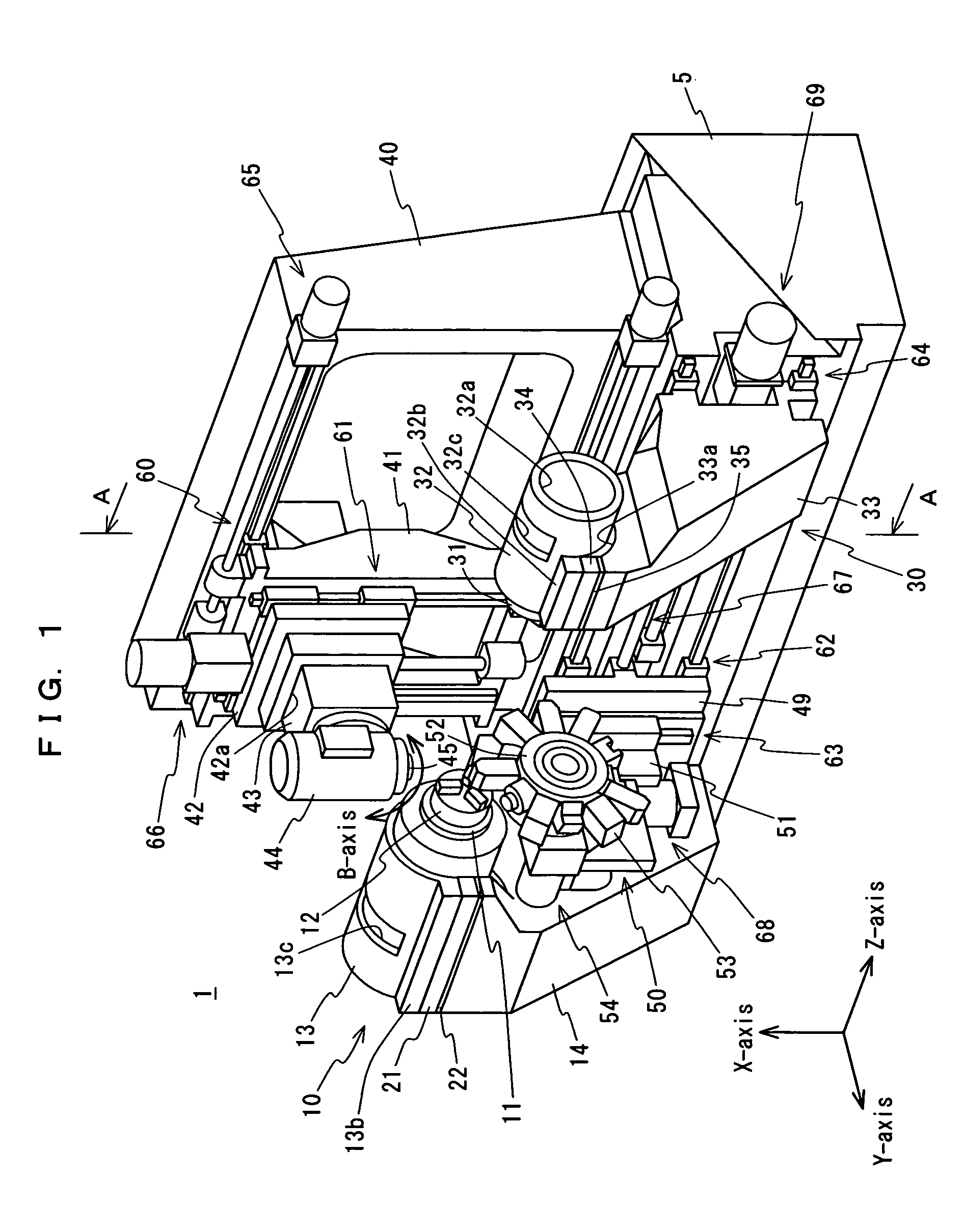
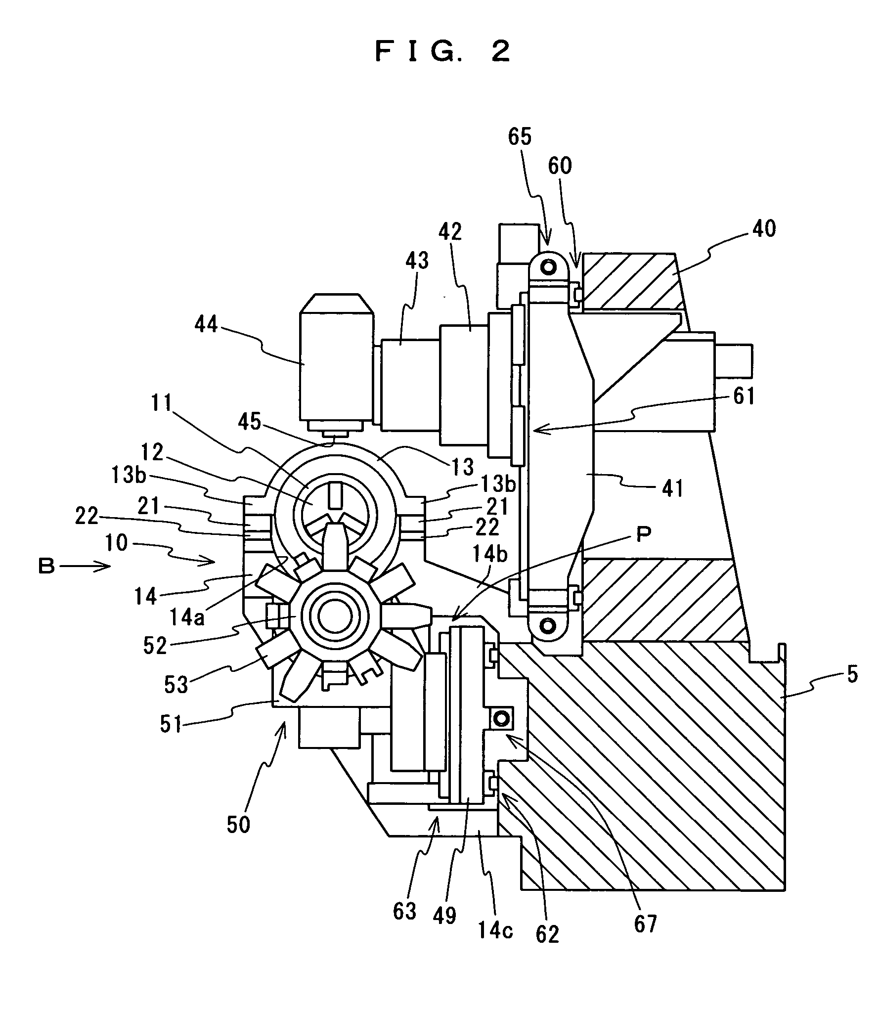
[0042] A preferred embodiment of the present invention will be described below with reference to the accompanying drawings. FIG. 1 is a perspective view showing a schematic configuration of an NC lathe in accordance with an embodiment of the present invention. FIG. 2 is a cross-sectional view taken in the arrow-indicated A-A direction of FIG. 1. FIG. 3 is a front view taken in the arrow-indicated B direction of FIG. 2. FIG. 4 is a side view taken in the arrow-indicated C direction of FIG. 3.

[0043] As shown in FIGS. 1 to 4, the NC lathe 1 in accordance with this embodiment comprises a bed 5 formed in a rectangular shape in the cross-section thereof so that the upper face is horizontal and so that the front face is vertical, a first headstock 10 fixed to the bed 5, a first main spindle 11 provided horizontally so that the axis line thereof is parallel with the front face of the bed 5 and supported by the first headstock 10 so as to be rotatable around the axis line thereof, a station...


PUM

PropertyMeasurementUnit
Heataaaaaaaaaa

Abstract

A lathe 1 comprises a bed 5, a headstock 10 having a housing 13 and a support base 14, a main spindle 11, a first tool rest 44, and a second tool rest 50. The support base 14 is formed so as to have a concave portion 14a on the upper portion thereof and so that the upper portion protrudes toward the second tool rest 50. The tool rest body 51 of the second tool rest 50 is configured so as to be movable into and out of a space formed downward from the upper portion of the support base 14. The housing 13 has a holding hole 13a for rotatably holding the main spindle 11, and installation portions 13b. The installation portions 13b are supported on the support base 14 in a state wherein a predetermined clearance is provided between the housing 13 and the concave portion 14a.

Description

BACKGROUND OF THE INVENTION [0001] 1. Field of the Invention [0002] The present invention relates to a lathe comprising a headstock for rotatably supporting a main spindle for holding a workpiece, and first and second tool rests for holding tools, the first and second tool rests being movable in predetermined feed directions. [0003] 2. Description of the Prior Art [0004] Conventionally, a machine tool having a structure shown in FIGS. 5 and 6 is known as a lathe. This lathe 100 comprises a bed 101 formed in the shape of a triangular prism becoming broad toward the bottom, and a first headstock 102, a second headstock 105, a first tool rest 110, a second tool rest 115 and the like provided on the bed 101 as shown in FIGS. 5 and 6 (refer to Japanese Unexamined Patent Publication No. 2002-59301). [0005] The first and second headstocks 102 and 105 rotatably support main spindles 103 and 106 around the axes thereof, respectively, and are provided with rotation drive devices (not shown) f...

Claims


Application Information

Patent Timeline
IPC IPC(8): B23B11/00B23B3/30B23B17/00B23B19/00B23B21/00B23Q1/00B23Q1/70
CPCB23B3/162B23Q1/70B23Q39/026B23Q2039/008B23Q2039/004Y10T82/2552Y10T82/2562Y10T82/2524Y10T82/2593Y10T82/26Y10T82/2566Y10T82/2508Y10T29/5114
Inventor TOKUMA, TSUTOMUSAKASHITA, YOSHINORI
Owner DMG MORI SEIKI CO LTD
Why Eureka
Try Eureka