Stud welding apparatus

a welding apparatus and stud technology, applied in the field of stud welding apparatus, can solve the problems of inability to handle cases, the welding gun is longer, and the stud is longer, and achieves the effect of shortening the stud length l, feeding smoothly, and simple welding gun structur

a welding apparatus and stud technology, applied in the field of stud welding apparatus, can solve the problems of inability to handle cases, the welding gun is longer, and the stud is longer, and achieves the effect of shortening the stud length l, feeding smoothly, and simple welding gun structur

US20050023252A1Inactive Publication Date: 2005-02-03NEWFREY

Image

  • Stud welding apparatus
  • Stud welding apparatus
  • Stud welding apparatus

Examples


Embodiment Construction

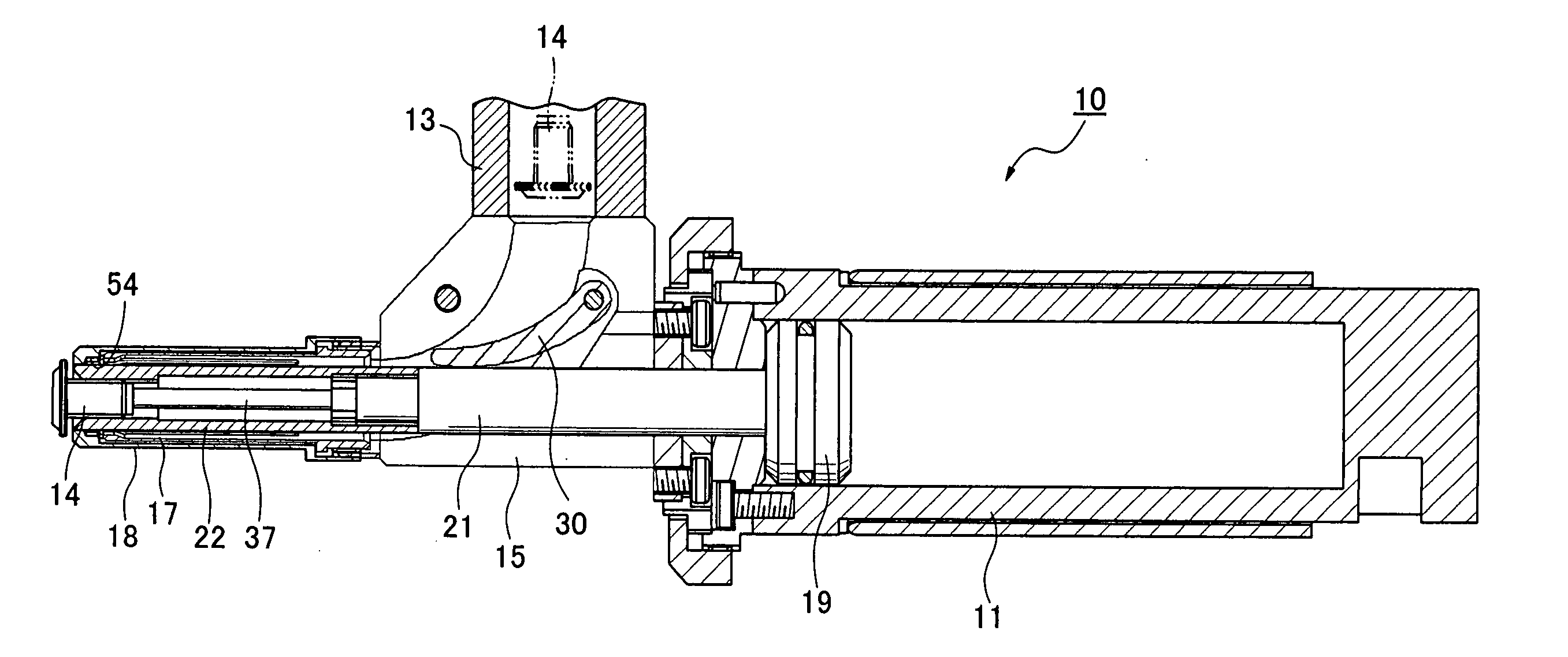
[0030] Embodiments of the present invention are now described with reference to the drawings. FIG. 4 diagrams the welding gun 10 of a stud welding apparatus. The stud welding apparatus has, besides the welding gun 10, a conventional electric power supply and a conventional controller (neither shown in the drawings). The welding gun 10 comprises an air cylinder 11 that forms the aft portion of the gun, a receiver 15, linked to a feed tube 13 and forming the central part of the welding gun, for receiving studs 14 that are sent under pressure by compressed air through the feed tube 13, a tubular first collet member 17 that forms the tip part of the welding gun 10, and a tubular collet cover 18. A piston 19 is deployed in the air cylinder 11. The piston 19 is moved to the tip end of the welding gun 10 by the supply of compressed air to the air cylinder 11 on the back side of the piston, and is returned to its original position by the supply of compressed air to the air cylinder 11 on th...


PUM

PropertyMeasurementUnit
diameteraaaaaaaaaa
elasticityaaaaaaaaaa
depthaaaaaaaaaa

Abstract

A welding gun 10 has a collet for holding a stud with a flange and a shank at the tip of the welding gun. The collet comprises a tubular first collet member 17, secured to the tip, which elastically opens to a larger diameter than the stud flange, for holding the flange at the tip, and a tubular second collet member 22, secured to the tip of a piston rod 21 which extends from an air cylinder 11 provided in the aft portion thereof toward the first collet member, for, by the movement of the piston, picking up, accommodating, and holding the shank of a stud fed with its flange to the fore inside the first collet member 17. A collet cover 18 is provided for enclosing the exterior of the first collet member 17, from the tip end thereof, with the tip of the collet cover 18 and the tip of the first collet member forming a flange edge carrying space 54 for accommodating and holding the edge of the stud flange and holding the end of the stud shank in an attitude such that it floats free from the inner wall of the first collet member.

Description

CROSS-REFERENCE TO RELATED APPLICATION [0001] This application claims the benefit of Japanese Application No. 2003-194363 filed Jul. 9, 2003, incorporated herein by reference. BACKGROUND OF THE INVENTION [0002] The present invention relates to a stud welding apparatus, and more particularly to a mechanism for mounting flanged studs, having a flange and a shank, to the tip of a welding gun. [0003] In Laid-Open Utility Model Application [Jikkai] No. S62-202977 / 1987, gazette publication (Patent Literature 1), a stud welding apparatus is disclosed which has a mechanism for mounting a flanged stud, having a flange and a shank, to the tip of a welding gun. In that stud welding apparatus, the collet for mounting a flanged stud to the tip of the welding gun is configured by a tubular first collet member that is secured to the tip of the welding gun for elastically holding the flange to the fore, and a tubular second collet member that is secured to a piston which extends from an air cylinde...

Claims


Application Information

Patent Timeline
03 Feb 2005
Publication
US20050023252A1
IPC
B23K9/20
CPC
B23K9/206; B23K9/20
Inventors
SAKODA, KANJI