Powder feed nozzle for laser welding

Inactive Publication Date: 2005-02-03
MTS SYSTEMS CORPORATION
View PDF43 Cites 19 Cited by
  • Summary
  • Abstract
  • Description
  • Claims
  • Application Information

AI Technical Summary

Problems solved by technology

If the dispersement profile of powder discharged from the nozzle is greater than the area of the molten pool or puddle, then catchment is poor since powder is dispersed to areas surrounding the molten pool in addition to the molten pool.
Powder that is deposited outside of the molten pool can have certain deleterious effect on the metallurgical qualities and performance of the result

Method used


Image

  • Powder feed nozzle for laser welding
  • Powder feed nozzle for laser welding
  • Powder feed nozzle for laser welding

Examples


Embodiment Construction

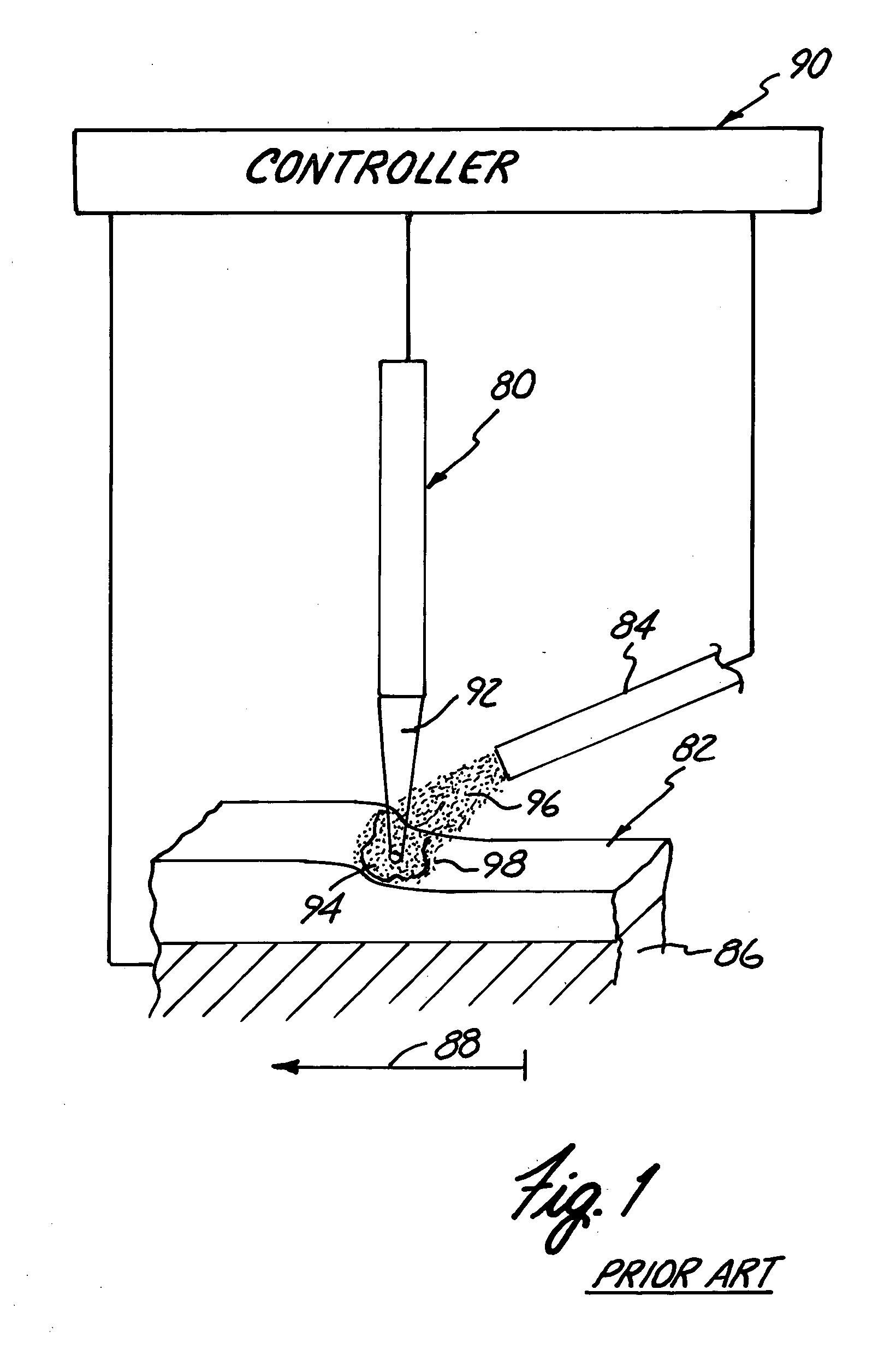
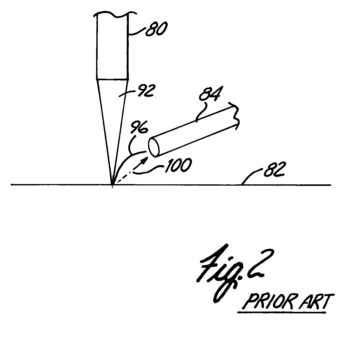
[0025]FIG. 1 schematically illustrates a laser welding operation for direct metal deposition for fabricating components of various shapes and forms. Laser welding uses a laser 80, such a CO2 laser to melt a powder, such as a titanium powder, deposited to a workpiece 82 from a powder source through a nozzle 84. Multiple layers of powder are deposited to workpiece 82 to form a fabricated component according to direct metal deposition techniques.

[0026] As shown in FIG. 1, workpiece 82 is supported on a welding table 86. In FIG. 1, welding table 86 movable supports the workpiece 82 as illustrated by arrow 88 relative to laser 80 and nozzle 84 for forming complex three dimensional components. Alternatively laser 80 and nozzle 84 can be movably supported relative to the workpiece 82 or fixed welding table 86. For deposition welding after each layer is formed, the nozzle 84 and laser 80 are indexed or raised to adjust the elevation of the nozzle 84 relative to the surface of the workpiece...


PUM


Abstract

A powder feed nozzle for laser welding applications including a multiple outlet nozzle tip for focusing a discharged powder stream. The multiple outlet nozzle tip disperses multiple outlet streams and includes a powder discharge outlet and at least one focus gas discharge outlet, radially spaced from the powder discharge outlet, for dispersing a powder stream and a gas stream. Powder flows from a powder source through a powder channel to discharge a powder stream. Focus gas flows through a focus gas channel angled relative to the powder channel to discharge a focus gas stream.

Description

CROSS-REFERENCE TO RELATED APPLICATION [0001] This application is a divisional of U.S. application Ser. No. 10 / 113,861, filed Apr. 1, 2003, and entitled “POWDER FEED NOZZLE FOR LASER WELDING”, which is a divisional of U.S. application Ser. No. 09 / 366,792, filed Aug. 4, 1999 and entitled “POWDER FEED NOZZLE FOR LASER WELDING”, which claims priority to U.S. Provisional Application Ser. No. 60 / 141,936, filed Jul. 1, 1999, and entitled “POWDER GAS FEED NOZZLE”.[0002] The Government may have certain rights to this invention under a Cooperative Research and Development Agreement (CRADA).BACKGROUND OF THE INVENTION [0003] The present invention relates to a nozzle for direct metal deposition and other laser welding applications. In particular, the present invention relates to a powder feed nozzle for use for direct metal deposition and other laser welding applications. [0004] Laser welding applications use high powered lasers or other high energy sources to melt deposited material for weldi...

Claims


Application Information

Patent Timeline
IPC IPC(8): B23K26/14
CPCB23K26/1411B23K26/144
Inventor PYRITZ, CLARENCE L.ARCELLA, FRANK G.HOUSE, MICHAEL A.
Owner MTS SYSTEMS CORPORATION
Why Eureka
Try Eureka