Ladle

a technology of ladles and cylinders, applied in the field of ladles, can solve the problems of unavoidable air drawn, unsatisfactory product quality, and increased production costs, and achieve the effect of significant improvement of efficiency

Inactive Publication Date: 2005-02-03
HONDA MOTOR CO LTD
View PDF1 Cites 4 Cited by
  • Summary
  • Abstract
  • Description
  • Claims
  • Application Information

AI Technical Summary

Benefits of technology

[0009] As the most important feature of the present invention, the inert gas supply nozzle of the ladle has its output-side end surface located in the molten material passageway portion and inclined upward, relative to the bottom surface of the molten material passageway portion, in a direction toward the molten material discharge opening. Thus, the output-side end surface of the nozzle is oriented toward the molten material discharge opening, the molten material flowing along the molten material passageway portion can be prevented from directly impinging on the nozzle's output-side end surface. As a result, the present invention can effectively eliminate the possibility of the output-side end portion of the nozzle being clogged with the molten material.
[0010] Further, with the output-side end surface of the nozzle, oriented toward the molten material discharge opening, the inert gas emitted from the nozzle can function to push the molten material along the passageway portion to the molten material discharge opening. Thus, at the last phase of the molten material pouring from the ladle into the holding furnace, in particular, the emitted inert gas can effectively push the molten material, remaining at and around the discharge opening, into the holding furnace, so that the molten material can be drained off the nozzle with significantly enhanced efficiency.

Problems solved by technology

Heretofore, during transfer of molten material from a melting surface to a molten material holding furnace, the molten material would produce hydrogen gas by drawing in vapor present in the air, and the thus produced hydrogen gas would then produce undesired cavities in workpieces cast by a casting process, therefore often resulting in unsatisfactory product quality.
However, with the technique of the Japanese patent, a great amount of air would be unavoidably drawn in as the molten material is relocated from the ladle to the funnel 1 that is interposed between the ladle and the molten material holding furnace.
For avoiding the clogging problem, there might be employed an approach of causing the supply section 7 to always emit inert gas; however, in this case, the production costs would increase considerably due to wasteful use of the inert gas.

Method used


Image

  • Ladle
  • Ladle
  • Ladle

Examples


Embodiment Construction

[0018] Example manner in which a ladle of the present invention is used will be explained first, prior to a detailed description about structural features of the ladle.

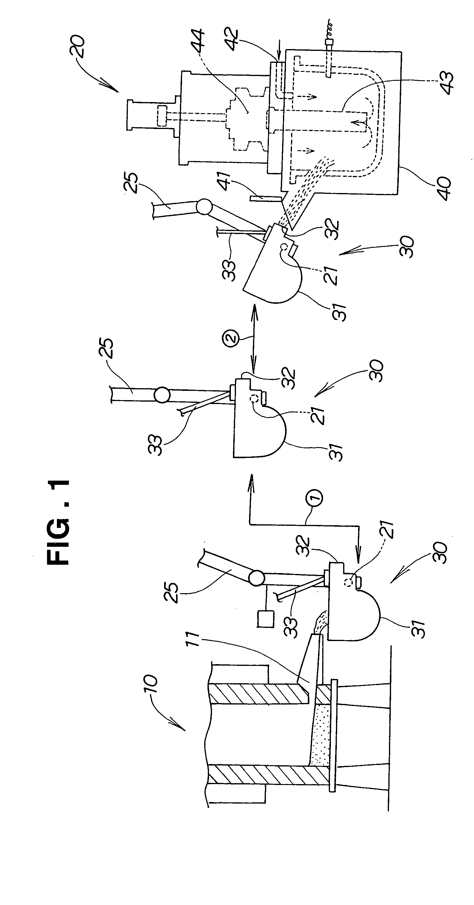
[0019]FIG. 1 is a view illustrating the example use of the ladle of the present invention. Generally, the ladle 30 is required because a casting machine 20 is installed a certain appropriate distance from an aluminum melting furnace 10. Namely, the ladle 30 is initially positioned to front a tapping hole 11 of the aluminum melting furnace 10 in proximity thereto, so as to receive molten material (in this case, molten aluminum) from the tapping hole 11. The ladle 30 is movable as depicted by arrow {circle over (1)} and arrow {circle over (2)}, through operation of a robot arm 25, so as to front a molten material holding furnace 40 in proximity thereto; the holding furnace 40 is attached to the casting machine 20.

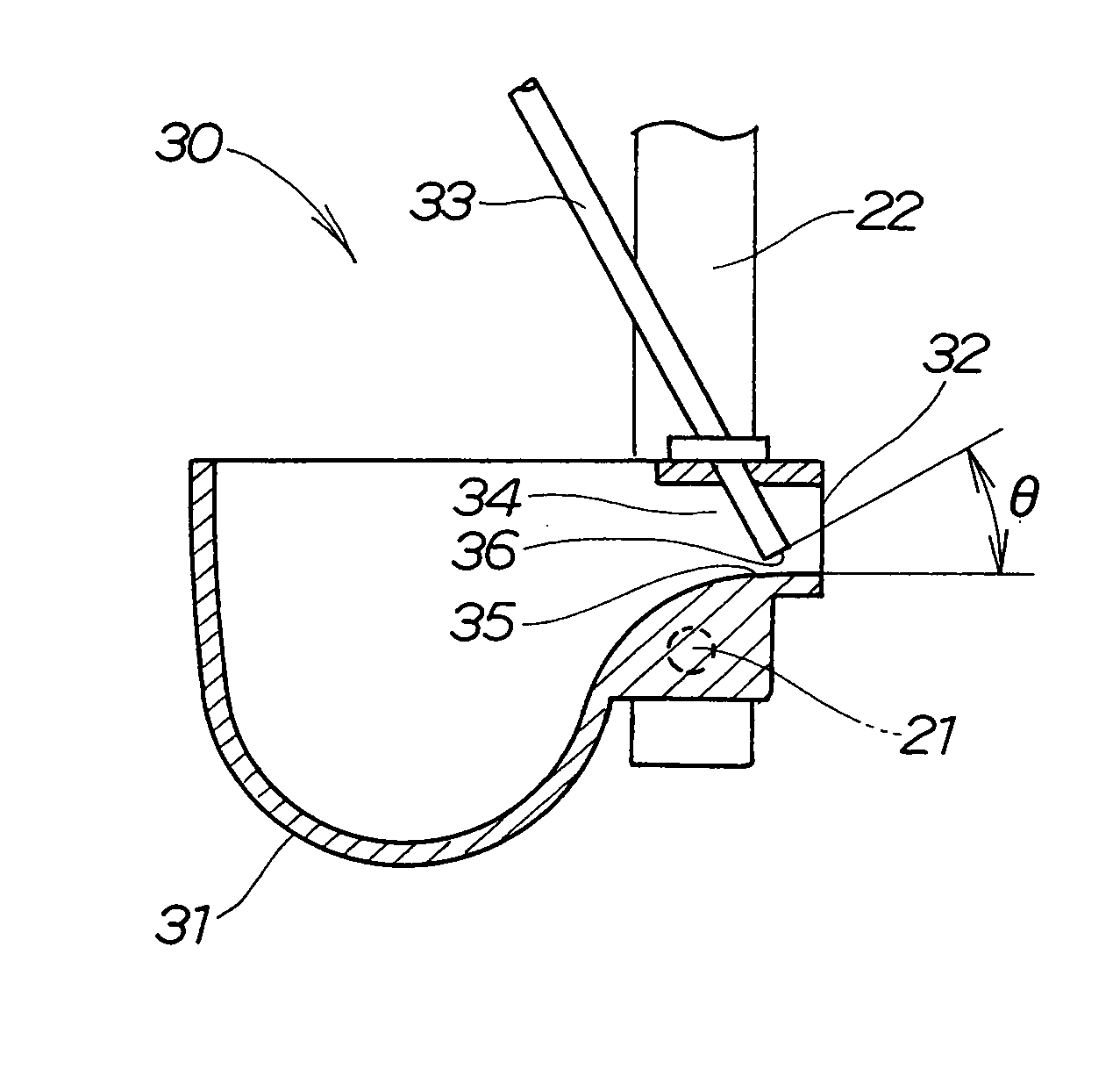
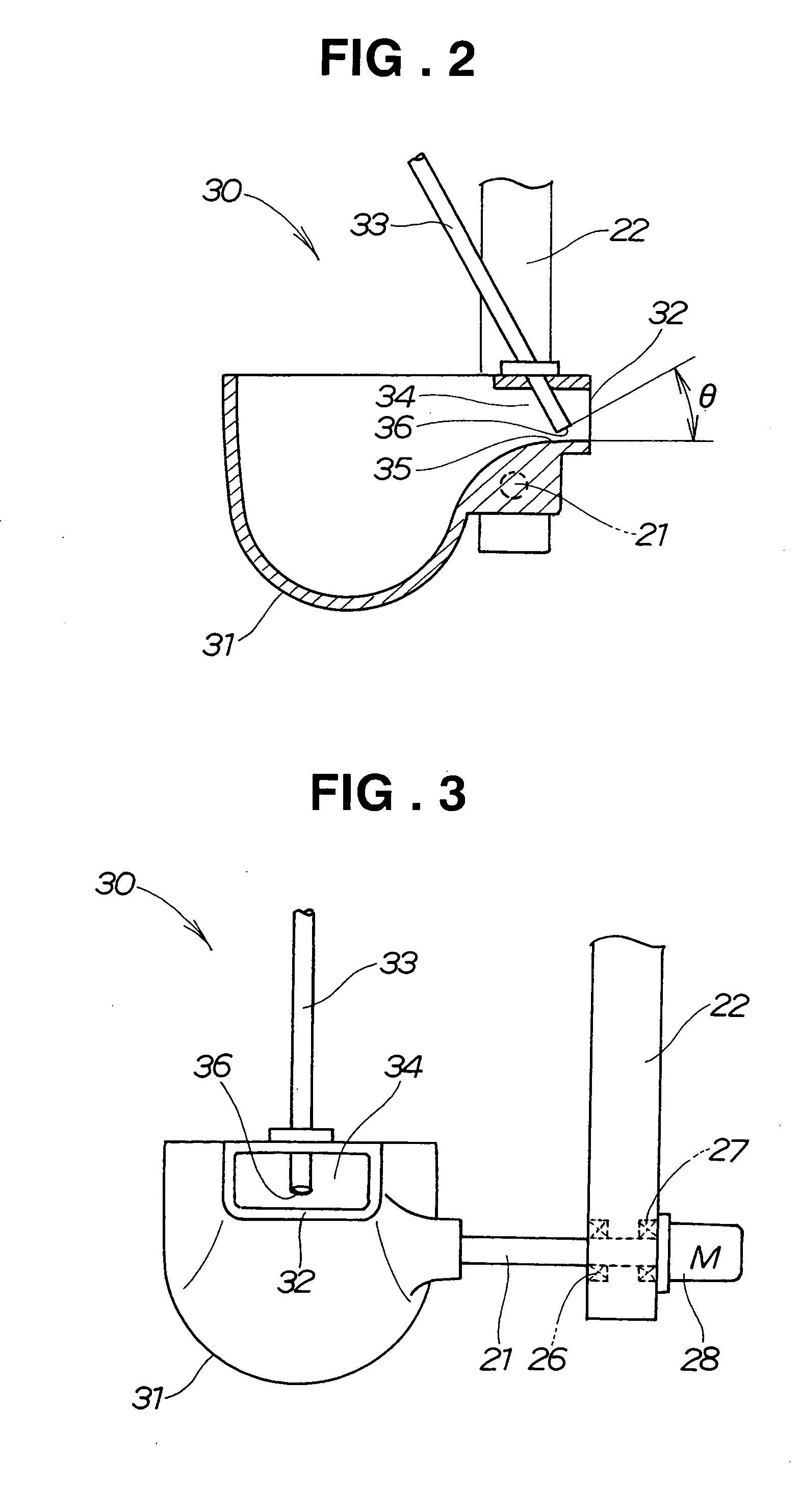
[0020] When molten material is to be poured from the ladle 30 into the molten material holding furnace 40,...


PUM

PropertyMeasurementUnit
angleaaaaaaaaaa
angleaaaaaaaaaa
angleaaaaaaaaaa

Abstract

Inert gas supply nozzle is mounted on a ladle body in such a manner its output-side end surface is inclined upward, relative to the bottom surface of a molten material passageway portion, in a direction toward a molten material discharge opening formed in the ladle body. Even when a portion of the molten material flows upward toward the nozzle's output-side end, that portion can be reliably prevented from entering the output-side end portion of the nozzle, by virtue of the inclined end surface. Thus, the inert gas supply nozzle can function to supply the inert gas into the molten material in a stable manner over a long period of time.

Description

FIELD OF THE INVENTION [0001] The present invention relates generally to ladles for supplying (or resupplying) molten metal (hereinafter referred to as “molten material”), such as molten aluminum, from melting furnaces to molten material holding furnaces. More particularly, the present invention relates to an improved ladle which allows inert gas to be emitted from a nozzle into molten material with enhanced efficiency. BACKGROUND OF THE INVENTION [0002] Heretofore, during transfer of molten material from a melting surface to a molten material holding furnace, the molten material would produce hydrogen gas by drawing in vapor present in the air, and the thus produced hydrogen gas would then produce undesired cavities in workpieces cast by a casting process, therefore often resulting in unsatisfactory product quality. [0003] In order to avoid the inconvenience, it has been generally conventional to perform a degassing process within the molten material holding furnace. Japanese Paten...

Claims


Application Information

Patent Timeline
Patent Type & Authority Applications(United States)
IPC IPC(8): B22D41/00B22D1/00B22D17/30B22D41/05C21C7/00C21C7/072F27B17/00F27D3/14F27D3/15F27D3/16
CPCB22D1/002C21C7/0075C21C7/072F27D3/16F27D3/14F27D3/1518F27B17/0016
Inventor TAKAHASHI, KIYOMIYAMAMOTO, TAKESHI
Owner HONDA MOTOR CO LTD
Why Eureka
Try Eureka