DC-DC converter circuits and method for reducing DC bus capacitor current

Active Publication Date: 2005-02-03
DELTA ELECTRONICS INC
View PDF4 Cites 14 Cited by
  • Summary
  • Abstract
  • Description
  • Claims
  • Application Information

AI Technical Summary

Benefits of technology

[0012] It is therefore an object of the present invention to propose the apparatus

Problems solved by technology

In general, the capacitor occupies a relatively large volume in a power converter and the cost of the capacitor is relatively high.
Th

Method used


Image

  • DC-DC converter circuits and method for reducing DC bus capacitor current
  • DC-DC converter circuits and method for reducing DC bus capacitor current
  • DC-DC converter circuits and method for reducing DC bus capacitor current

Examples


Embodiment Construction

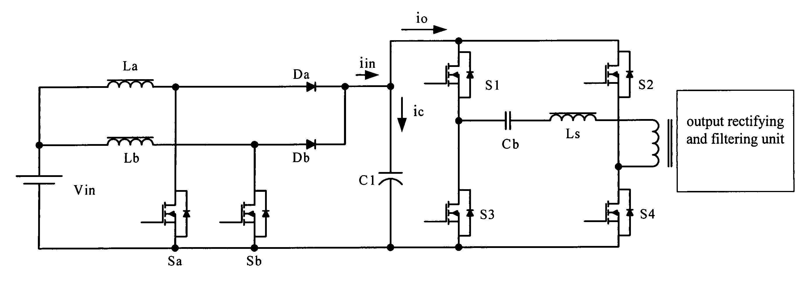
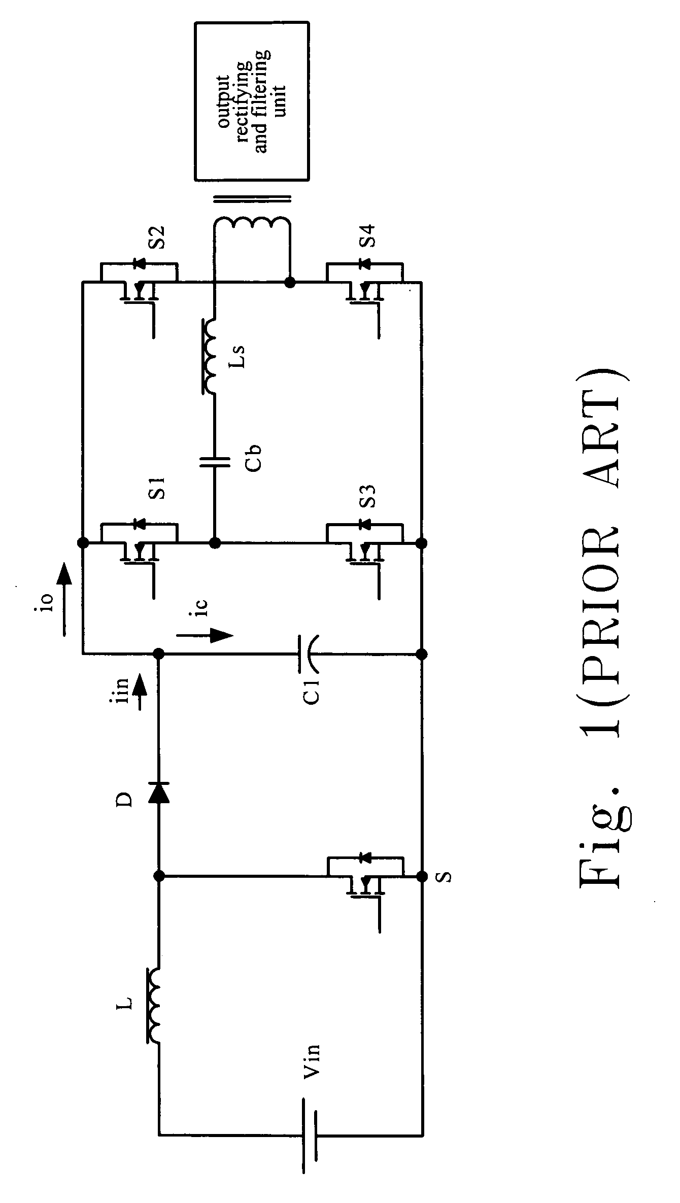
[0035] To decrease the DC Bus capacitor current, the present invention improves the topology design of the multi-stage converter. The main circuit configuration having the double-frequency PFC circuit in the front-end and the phase-shifted full-bridge DC-DC converter in the back-end is proposed in the present invention as shown in FIG. 4. In which, the back-end of the system employs the same circuit as shown in FIG. 1, the main difference between the two is that the PFC circuit in the front-end is improved from a single configuration to the dual configuration. In FIG. 4, the Vin, the inductors La and Lb, the power switches Sa and Sb, the power diodes Da and Db, and the DC Bus capacitor C1 constitute the PFC unit. The elements La, Sa, and Da correspond to the elements Lb, Sb, and Db, and each group respectively forms an independent unit. The main operational principles of the proposed circuit are: 1. There is a difference of 180 degrees between corresponding phase angles of the contr...


PUM


Abstract

An apparatus for reducing the heat losses caused by the DC Bus capacitor current is proposed. The apparatus includes: a double frequency boost converter circuit having two boost converter circuits coupled in parallel, in which two switches, respectively disposed on the two boost converter circuits, are turned on and off alternately to produce an output current having a frequency twice that of control signals of the two switches, and to offer a DC bus respectively, a full-bridge DC-DC converter coupled to an output terminal of the double frequency boost converter circuit for transforming an output of the DC bus to a DC voltage, and a DC bus capacitor coupled to the double frequency boost converter circuit and the full-bridge DC-DC converter in parallel for balancing two corresponding transient powers of the double frequency boost converter circuit and the full-bridge DC-DC converter respectively.

Description

FIELD OF THE INVENTION [0001] The present invention relates to the apparatus and the method for reducing the heat losses caused by the DC Bus capacitor current. More specifically, this invention relates to the proposed DC-DC converter circuits having relatively lower DC Bus capacitor current and the method so as to decrease the heat losses and to improve the efficiency. BACKGROUND OF THE INVENTION [0002] For the power converters, usually the multi-stage circuit configurations would be employed when the reliability and the simplicity of production are under consideration. The aforementioned multi-stage configurations almost always have the DC Bus, and the DC Bus usually is coupled to a capacitor having a relatively high capacitance in parallel. For example, usually the two-stage configuration having a DC Bus would be employed in the power source of the communication system. Usually, the front-end is a power factor correction (PFC) circuit, the back-end is a DC-DC converter, and the D...

Claims


Application Information

Patent Timeline
IPC IPC(8): H02M1/00H02M3/158H02M3/337
CPCH02M1/4208H02M3/1584Y02B70/126H02M2001/007H02M3/337Y02B70/10H02M1/007H02M3/33573
Inventor YING, JIANPINGZHANG, QINGYOUQIU, AIBINLIU, TENGGUO, XINGKUANZENG, JIANHONG
Owner DELTA ELECTRONICS INC
Why Eureka
Try Eureka