Voltage controlled oscillator programmable delay cells

a technology of voltage control and delay cell, applied in pulse generators, pulse manipulation, pulse techniques, etc., can solve the problems of increasing the operating frequency range of the pll circuit, reducing the power supply voltage of the integrated circuit, etc., and extending the operating frequency range. , the time delay characteristic of the delay cell can be greatly extended.

Inactive Publication Date: 2005-02-03
ALTERA CORP
View PDF13 Cites 4 Cited by
  • Summary
  • Abstract
  • Description
  • Claims
  • Application Information

AI Technical Summary

Benefits of technology

[0004] A delay cell (e.g., for use in the voltage controlled oscillator (“VCO”) of a PLL) includes a plurality of load resistance transistors connectable in parallel with one another, a plurality of bias current transistors connectable in parallel with one another, and a switching transistor connected in series between the load resistance transistors and the bias current transistors. Switching circuitry allows the number of the load resistance transistors that are actually operating in parallel to be selected. Other switching circuitry similarly allows the number of the bias current transistors that are actually operating in parallel to be similarly selected. This ability to essentially reconfigure the delay cell allows the operating range (i.e., the time delay characteristic) of the delay cell to be greatly extended. A VCO may include a plurality of such delay cells connected in a closed loop series. The extended operating range of the delay cells similarly greatly extends the operating frequency range of a VCO made up of such cells. The same is true for the operating range of a PLL that includes such a VCO.

Problems solved by technology

At the same time, power supply voltages for integrated circuits are decreasing, making it more difficult to extend the operating range of PLL circuits.

Method used


Image

  • Voltage controlled oscillator programmable delay cells
  • Voltage controlled oscillator programmable delay cells
  • Voltage controlled oscillator programmable delay cells

Examples


Embodiment Construction

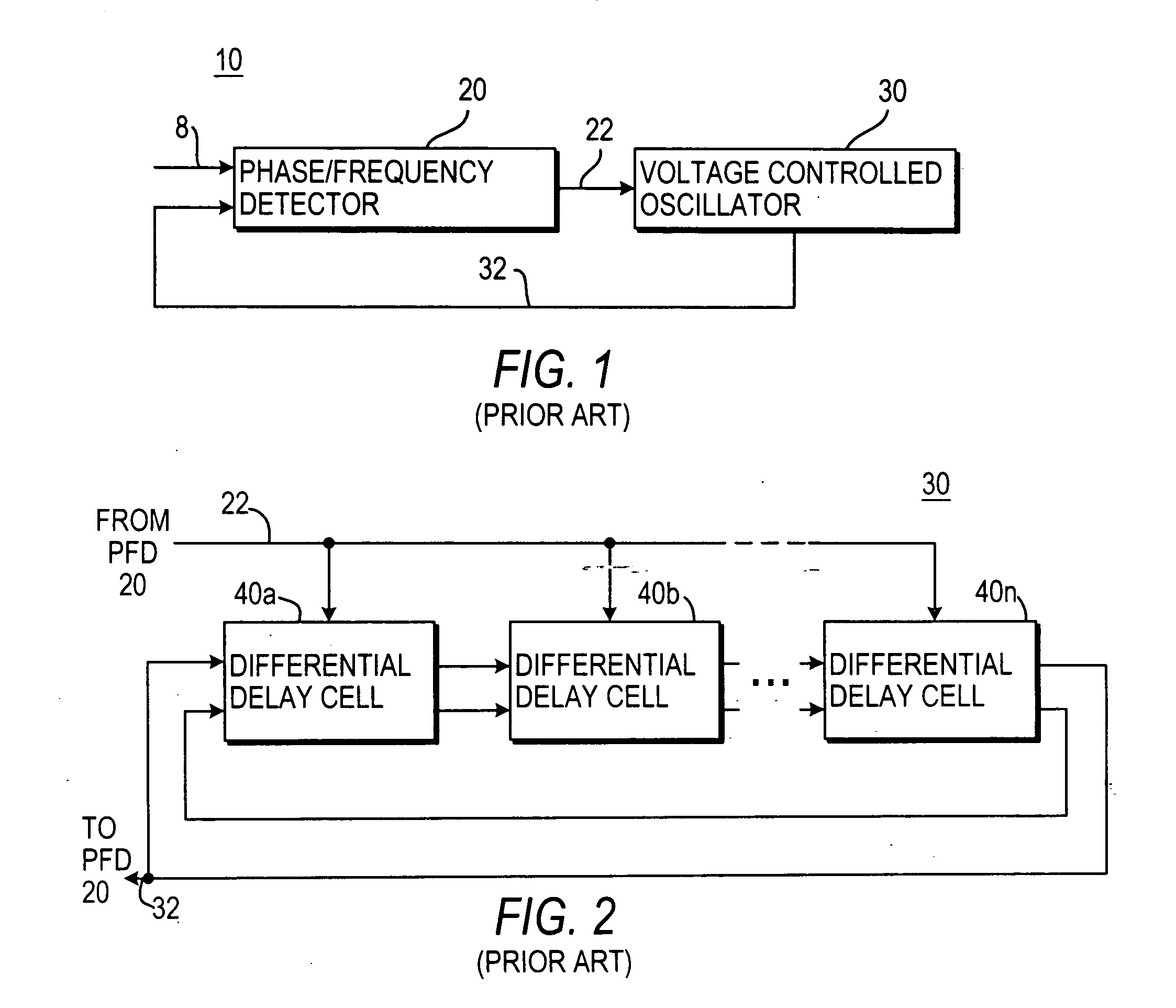
[0016] In the illustrative, conventional, PLL circuit 10 shown in FIG. 1, phase / frequency detector (“PFD”) circuit 20 receives an input signal via input lead 8. Signal 8 is a time-varying signal such as a binary digital signal conveying data represented by different voltage levels and / or by voltage level transitions. PFD 20 compares the phase and frequency of signal 8 to the phase and frequency of a signal fed back to PFD 20 from VCO 30 via lead 32. Based on that comparison, PFD 20 produces one or more output signals 22 for controlling VCO 30 to make the phase and frequency of signal 32 more closely match the phase and frequency of signal 8. For example, signal 8 may be a CDR (clock data recovery) data signal, and PLL 10 may be operated to provide a clock signal recovered from the CDR data signal. (The recovered clock signal can be signal 32 or a signal synchronized with but shifted in phase relative to signal 32, depending on the application.) If PFD 20 detects that signal 32 is to...


PUM


Abstract

A delay cell has selectable numbers of parallel load resistance transistors operable in parallel, and a similarly selectable number of bias current transistors connectable in parallel. The delay cell is preferably differential in construction and operation. A voltage controlled oscillator (“VCO”) includes a plurality of such delay cells connected in a closed loop series. Phase locked loop (“PLL”) circuitry includes such a VCO controlled by phase/frequency detector circuitry. The PLL can have a very wide range of operating frequencies as a result of the ability to control the number of load resistance transistors and bias current transistors that are active or inactive in each delay cell. Such activation/deactivation may be programmable or otherwise controlled.

Description

[0001] This application is a continuation of application Ser. No. 10 / 099,707, filed Mar. 13, 2002, which claims the benefit of U.S. provisional patent application No. 60 / 323,249, filed Sep. 18, 2001. These prior applications are hereby incorporated by reference herein in their entireties.BACKGROUND OF THE INVENTION [0002] This invention relates to voltage controlled oscillator (“VCO”) circuits, and more particularly to voltage controlled oscillator circuits that can be programmed to operate in any of several frequency ranges over a very wide band of such frequency ranges. [0003] Phase locked loop (“PLL”) circuitry is frequently used for such purposes as helping to retrieve data from a signal that may vary in frequency and / or phase. The PLL may be in relatively general-purpose circuitry such as a programmable logic device (“PLD”) that may need to support signaling at any frequency in a wide range of frequencies. (For examples of PLDs employing PLLS, see Aung et al. U.S. patent applic...

Claims


Application Information

Patent Timeline
Patent Type & Authority Applications(United States)
IPC IPC(8): H03H11/26H03K3/03H03K3/354H03K5/13H03L7/099H03L7/10
CPCH03K3/0322H03K3/354H03L7/10H03L7/0995H03K5/133
Inventor ANDRASIC, STJEPAN WILLIAMPATEL, RAKESH H.LEE, CHONG H.
Owner ALTERA CORP
Why Eureka
Try Eureka