

Very low resistance electrical interfaces to conductive loaded resin-based materials
a technology of conductive plastics and electrical interfaces, which is applied in the direction of coupling contact members, shielding material radiating elements, chemistry apparatuses and processes, etc., can solve the problems of poor connectivity, difficult and expensive formation of electrical interfaces with conductive plastics, and limited use of materials, etc., to achieve effective electrical interfaces
- Summary
- Abstract
- Description
- Claims
- Application Information
AI Technical Summary
Benefits of technology
Problems solved by technology
Method used
Image

Examples
embodiment 100
[0044] Referring now to FIG. 7, a second preferred embodiment 100 of the present invention is shown. More particularly, one embodiment 100 of a method to form the electrical interface of FIG. 1 is illustrated. Referring again to FIG. 1, an interface pin 106 of a magnetizing metal is provided. For example, the interface pin 106 comprises iron according to one embodiment. The metal pin 106 is magnetized. According to one embodiment, the pin 106 is placed into contact with a strong magnet 104 to magnetize the pin 106. The pin core 106 is then plated with a solderable metal layer 110 according to another embodiment. Alternatively, the pin 106 may be non-plated. According to yet another alternative, the metal plating is performed prior to the magnetizing step. According to yet another embodiment, the pin 106 is not plated. In another embodiment, the pin 106 is a plurality of pins, terminals, sockets, or the like.
[0045] The magnetized pin 106 and 110 is next placed into a holding fixture ...
embodiment 140
[0046] Referring now to FIG. 8, a third preferred embodiment 140 of the present invention is shown. More particularly, another embodiment 140 of a method to form the electrical interface of FIG. 1 is illustrated. Once again an interface pin with a magnetizable core 144 is provided. The interface pin core 144 comprises iron according to one embodiment. The pin core 144 is plated with a solderable metal layer 148 according to another embodiment. Alternatively, the pin 144 may be non-plated. In another embodiment, the pin 144 is a plurality of pins, terminals, sockets, or the like. The pin 144 and 148 is next placed into a holding fixture of a molding apparatus 152. While in the mold apparatus 152, the pin 144 and 148 is placed into contact with a magnet 156. In this embodiment a small, weak magnet may be used to provide a temporary magnet field through the pin 144 and 148.
[0047] Molten conductive loaded resin-based material 160 is then injected into the mold 152 such that the pin 144 ...
embodiment 200
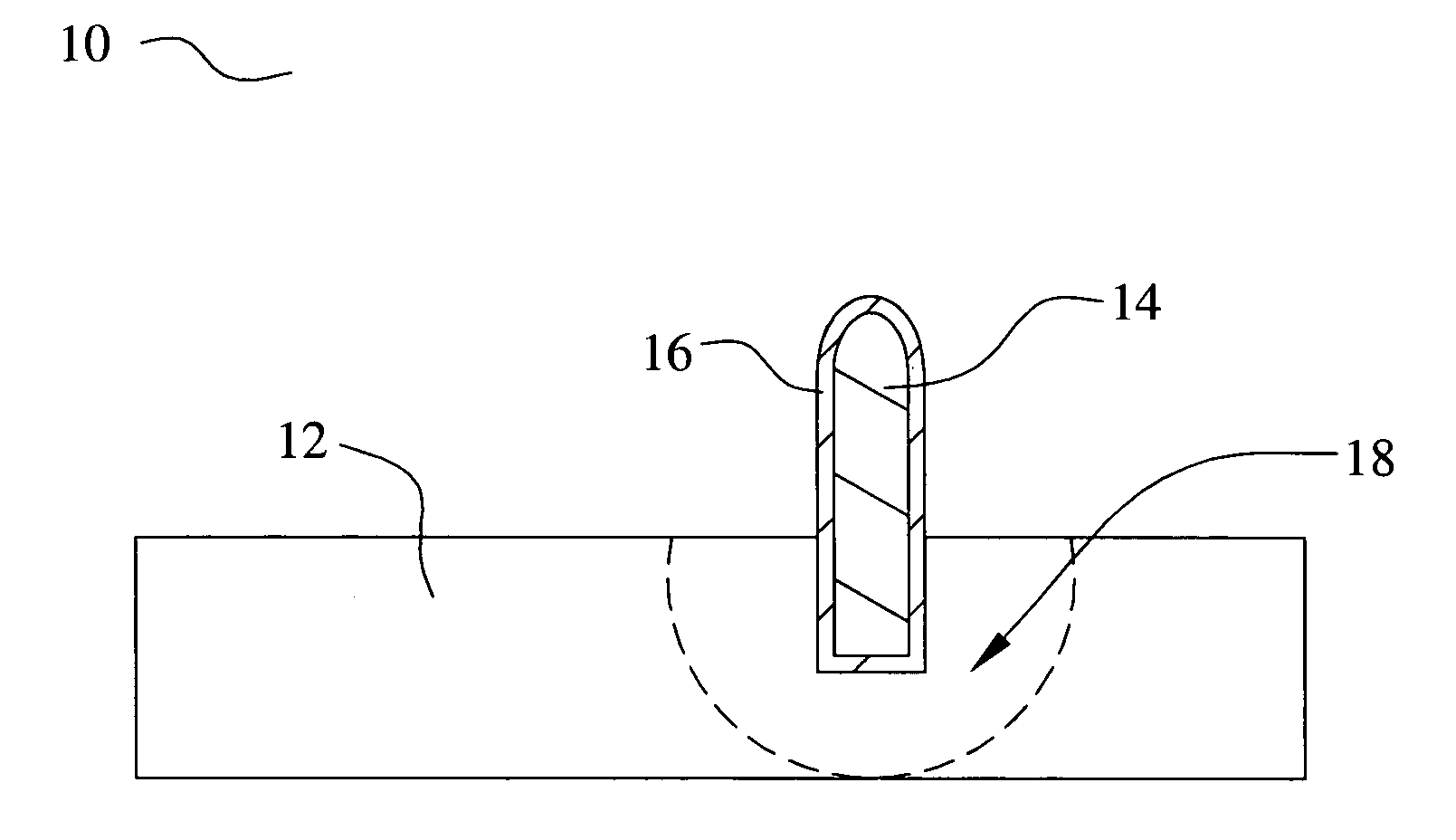
[0049] Referring now to FIG. 9, a fourth preferred embodiment 200 of the present invention is illustrated. In this embodiment, a conductive terminal 204 is embedded into the conductive loaded resin-based material device 208 after the device 208 has been molded. According to the illustrated embodiment, the conductive terminal 204 comprises a metal screw 204 that is driven into the conductive loaded resin-based material device 208 such that the shaft of the screw 204 intersects the conductive matrix. Alternatively, the conductive terminal 204 comprises a pin, nail, staple, or the like, that is mechanically driven into the conductive loaded resin-based device 208. After the conductive terminal 204 is embedded, a connector tab 212 is solder 216 bonded to the terminal 204 according to the illustration. In this case, the conductive terminal 204 comprises, or is plated with, a solderable metal such as copper or brass.
PUM
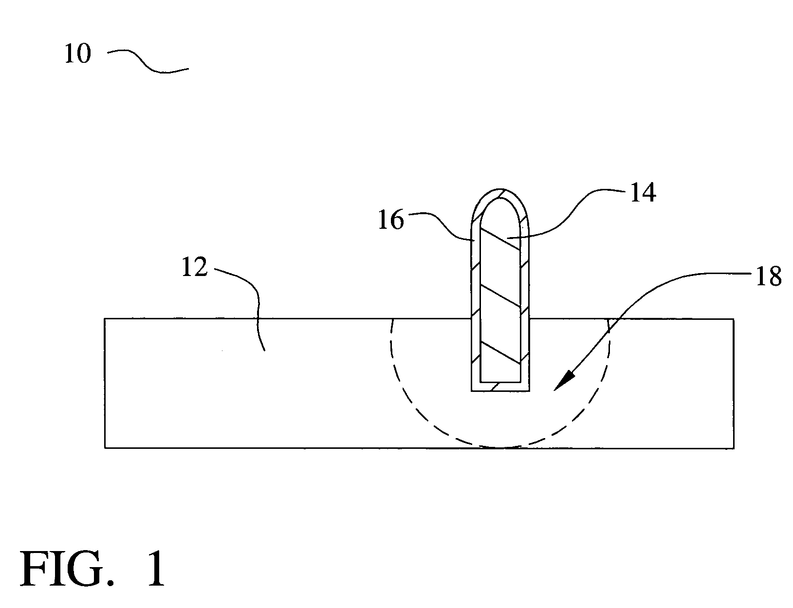
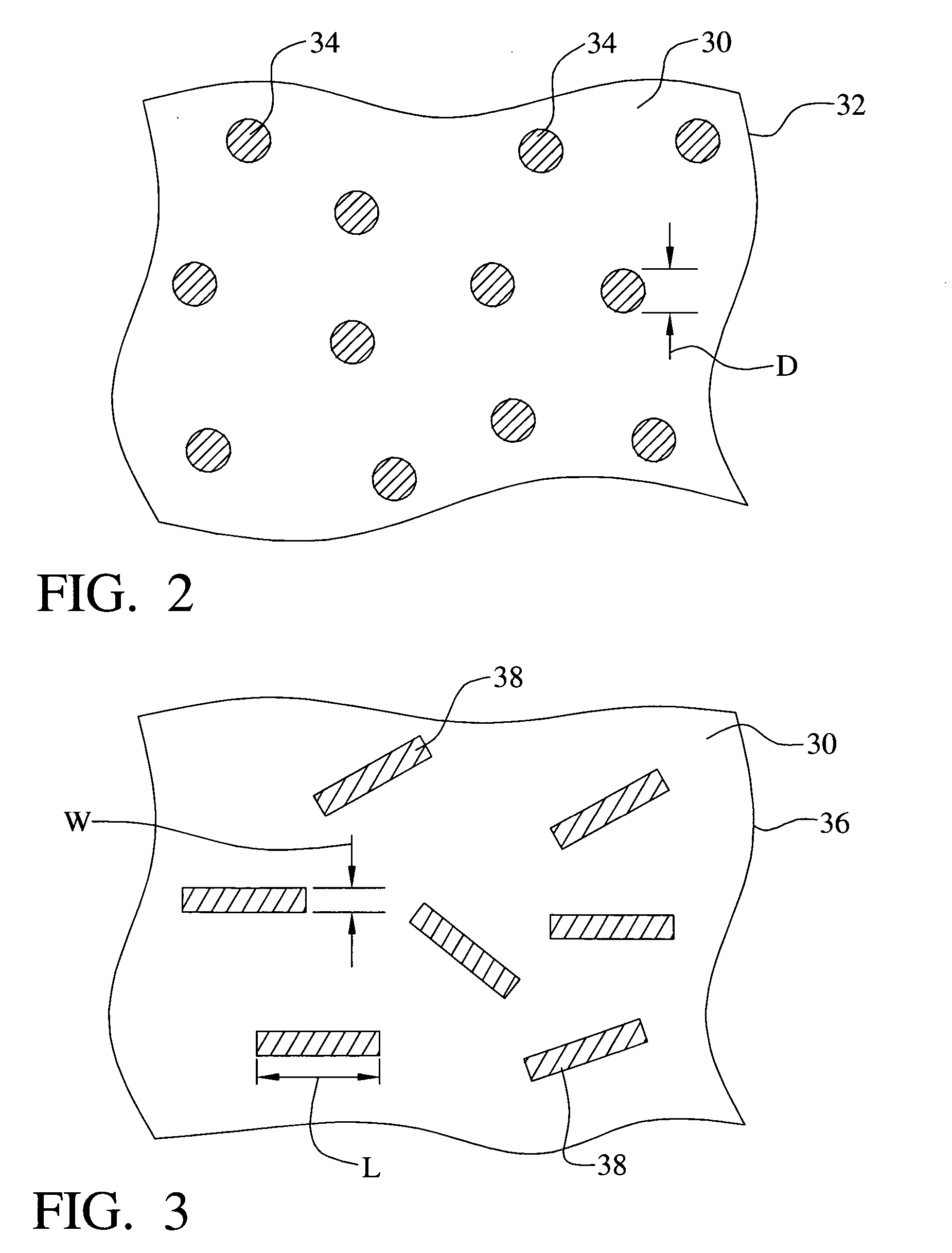
| Property | Measurement | Unit |
|---|---|---|
| diameter | aaaaa | aaaaa |
| diameter | aaaaa | aaaaa |
| length | aaaaa | aaaaa |
Abstract
Description
Claims
Application Information