Method and device for optical navigation

a technology of optical navigation and optical navigation, applied in the direction of distance measurement, instruments, coding, etc., can solve the problems of typical current optical navigation devices that are dominated by painted metal, and achieve the effects of preserving image quality, reducing the number of optical navigation devices, and improving signal quality

Active Publication Date: 2005-02-03
PIXART IMAGING INC
View PDF64 Cites 98 Cited by
  • Summary
  • Abstract
  • Description
  • Claims
  • Application Information

AI Technical Summary

Benefits of technology

[0006] In accordance with the invention, a preselected angular distribution of reflected light is captured by the detector of an optical navigation device. Typically, the detector of the optical navigation device is positioned to capture the specular reflection from the surface. The specular reflection creates an image of the surface that differs from both shadow pattern images and speckle patterns. Specular reflection typically provides a better signal compared to the shadow pattern image approach. This allows high contrast images to be obtained even on extremely smooth surfaces. Additionally, image quality is preserved with respect to Lambertian surfaces because light is still scattered into the specular direction. The specular reflection images depend on the wavelength of the illumination source; typically the contrast of the specular reflection images increases as the bandwidth of the illumination source decreases, therefore laser based illumination affords the highest contrast.
[0007] In accordance with the invention, power requirements may be reduced by using an illumination source whose wavelength lies at the peak of the detector responsivity curve. The contrast of the specular reflection images depends on the degrees of spatial and temporal coherence of the illumination source. Use of a narrow band illumination source such as a vertical cavity surface emitting laser (VCSEL) or narrow band light emitting diode (LED) provides enhanced image contrast at reduced power. Increasing the bandwidth induces averaging resulting in lower contrast as the returns from individual scatterers illuminated at different wavelengths add incoherently. Therefore, in accordance with the invention, the bandwidth of the illumination source must be narrow enough to have sufficient coherent interference to obtain images of sufficiently high contrast to for reliable optical navigation. For example, an illumination source having a bandwidth on the order of 20 nm provides sufficient contrast for optical navigation on a large range of surfaces in the office desktop environment.

Problems solved by technology

Smooth surfaces such as whiteboard, high gloss paper, plastic or painted metal present functional challenges to typical current optical navigation devices.

Method used


Image

  • Method and device for optical navigation
  • Method and device for optical navigation
  • Method and device for optical navigation

Examples


Embodiment Construction

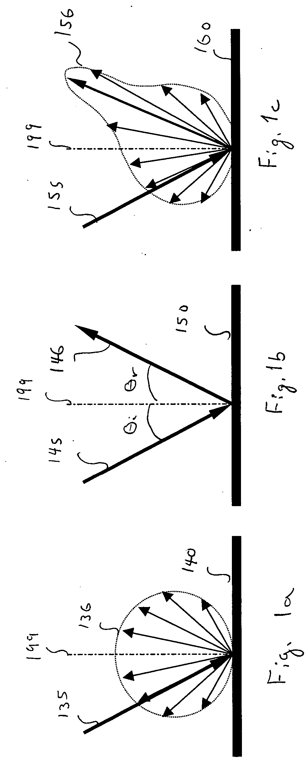
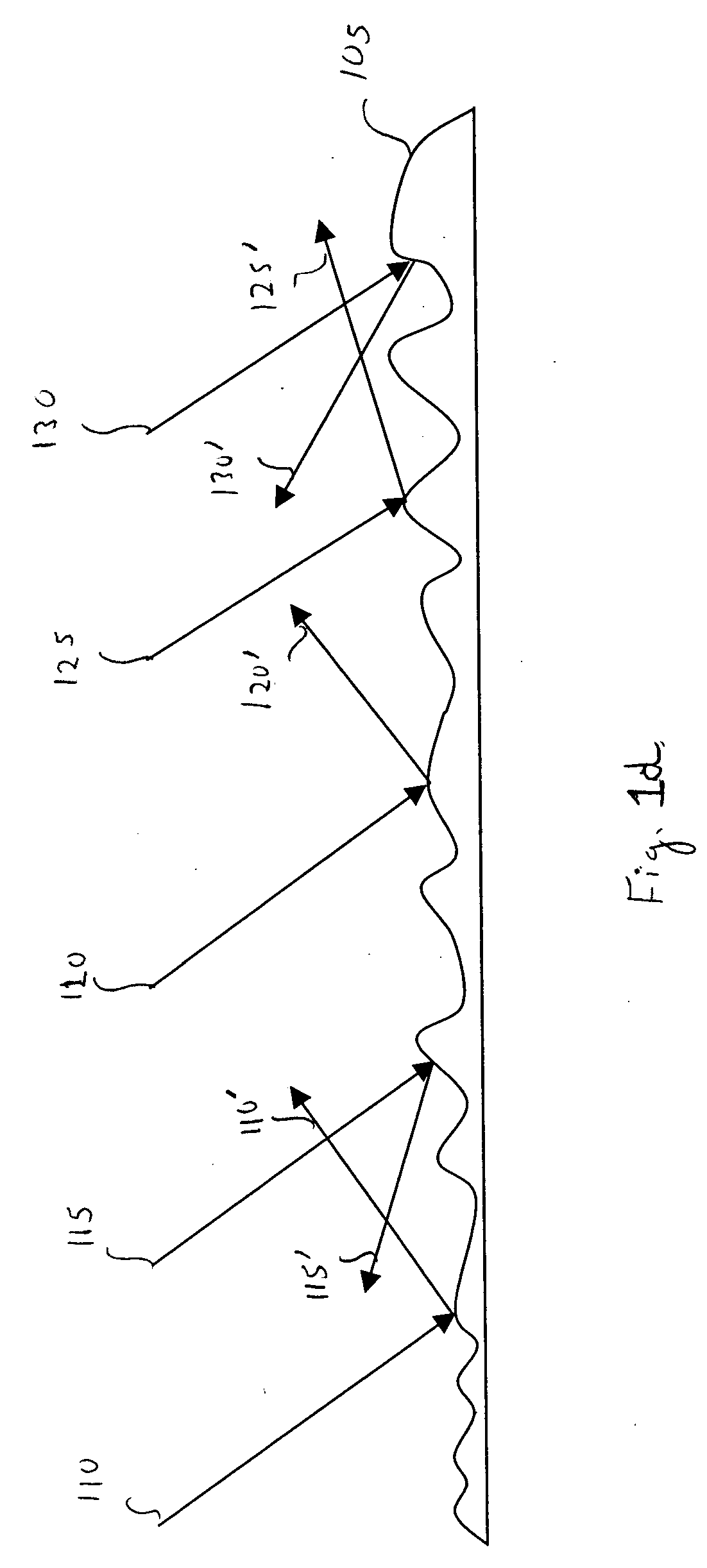
[0017] If a light beam is incident on a smooth surface, the light rays of the incident beam reflect and remain concentrated in a bundle upon leaving the smooth surface. However, if a surface is microscopically rough, then the light rays reflect and scatter in many different directions. The spatial frequency corresponding to the surface roughness may be on the scale of the illumination wavelength. Each individual ray follows the law of reflection. However, in the case of a rough surface each individual ray meets a portion of the surface that has a different orientation. Therefore, the surface normal is different for different incident light rays. Hence, when the individual rays reflect according to the law of reflection, the individual rays scatter in different directions. Furthermore, when either a coherent or a quasi-coherent illumination is applied, high contrast intensity patterns produced by interference among the reflected and the scatter light may be observed in the specular r...


PUM


Abstract

An method and device suitable for navigation on a wide variety of surfaces is introduced. Specular reflection is used to determine relative motion over typical surfaces. A specific application is a computer mouse.

Description

TECHNICAL FIELD [0001] This application relates to motion sensing devices and more particularly to devices, systems and methods for using specular reflection images to determine relative motion. BACKGROUND OF THE INVENTION [0002] Optical relative motion detection devices typically utilize image correlation techniques to determine relative motion between the navigation device and a surface by capturing images of the surface as the navigation device passes over the surface or as the surface moves past the navigation device. Both the displacement and the direction of the relative motion of the navigation device with respect to the surface are determined by comparing one image with the following image. Typically, intensity variations due to shadows cast on the surface are detected and the sensitivity and applicability of this technique depend on the intensity contrast in the captured images. Relative motion navigation devices are used, for example, for computer screen pointer (e.g. mous...

Claims


Application Information

Patent Timeline
Patent Type & Authority Applications(United States)
IPC IPC(8): G06F3/03G06F3/033
CPCG06F3/0317
Inventor XIE, TONGDEPUE, MARSHALL T.BANEY, DOUGLAS M.
Owner PIXART IMAGING INC
Why Eureka
Try Eureka