Self-calibrating strobe signal generator

a strobe signal and generator technology, applied in the field of self-calibrating strobe signal generators, can solve the problems of consuming substantial floor space within an ic, employing relatively complex logic, and external test equipment capable of testing path delays

Inactive Publication Date: 2005-02-03
CREDENCE SYSTEMS
View PDF14 Cites 29 Cited by
  • Summary
  • Abstract
  • Description
  • Claims
  • Application Information

AI Technical Summary

Problems solved by technology

However, in many cases external test equipment capable of testing path delays will not be able to directly access the input and / or the output terminal of a signal path within an IC to be tested.
One drawback to BIST circuit 10 is that to evaluate equation [1] above during the self-calibration process controller 27 employs relatively complex logic, including an arithmetic logic unit (ALU) preferably capable of handling floating point divisions and subtractions.
Such complex logic can consume substantial floor space within an IC and may require many clock cycles to perform the necessary calculations once the count data for those calculations has been acquired.
The calibration procedure can also be somewhat inaccurate when programmable delay circuit 26 provides substantial residual delay when nominally set for zero delay during the calibration process as is typically the case for conventional programmable delay circuits.

Method used


Image

  • Self-calibrating strobe signal generator
  • Self-calibrating strobe signal generator
  • Self-calibrating strobe signal generator

Examples


Embodiment Construction

The present invention relates to self-calibrating strobe signal generator. The specification below describes an exemplary strobe signal generator in accordance with the invention in the context of an application within a built-in self-test (BIST) circuit for measuring path delays within an integrated circuit (IC). However, those of skill in the art will appreciate that a self-calibrating strobe signal generator in accordance with the invention can be employed in other applications.

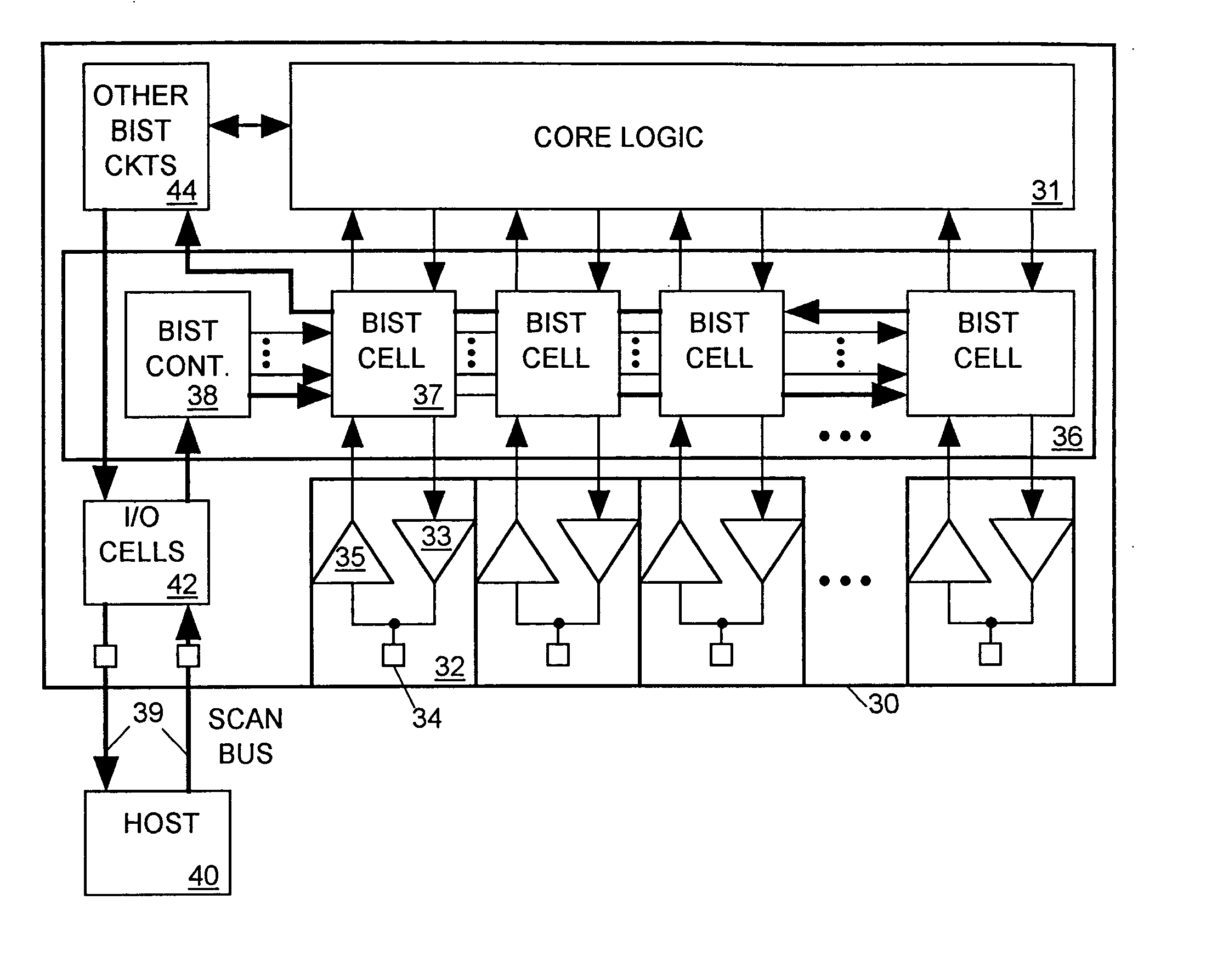
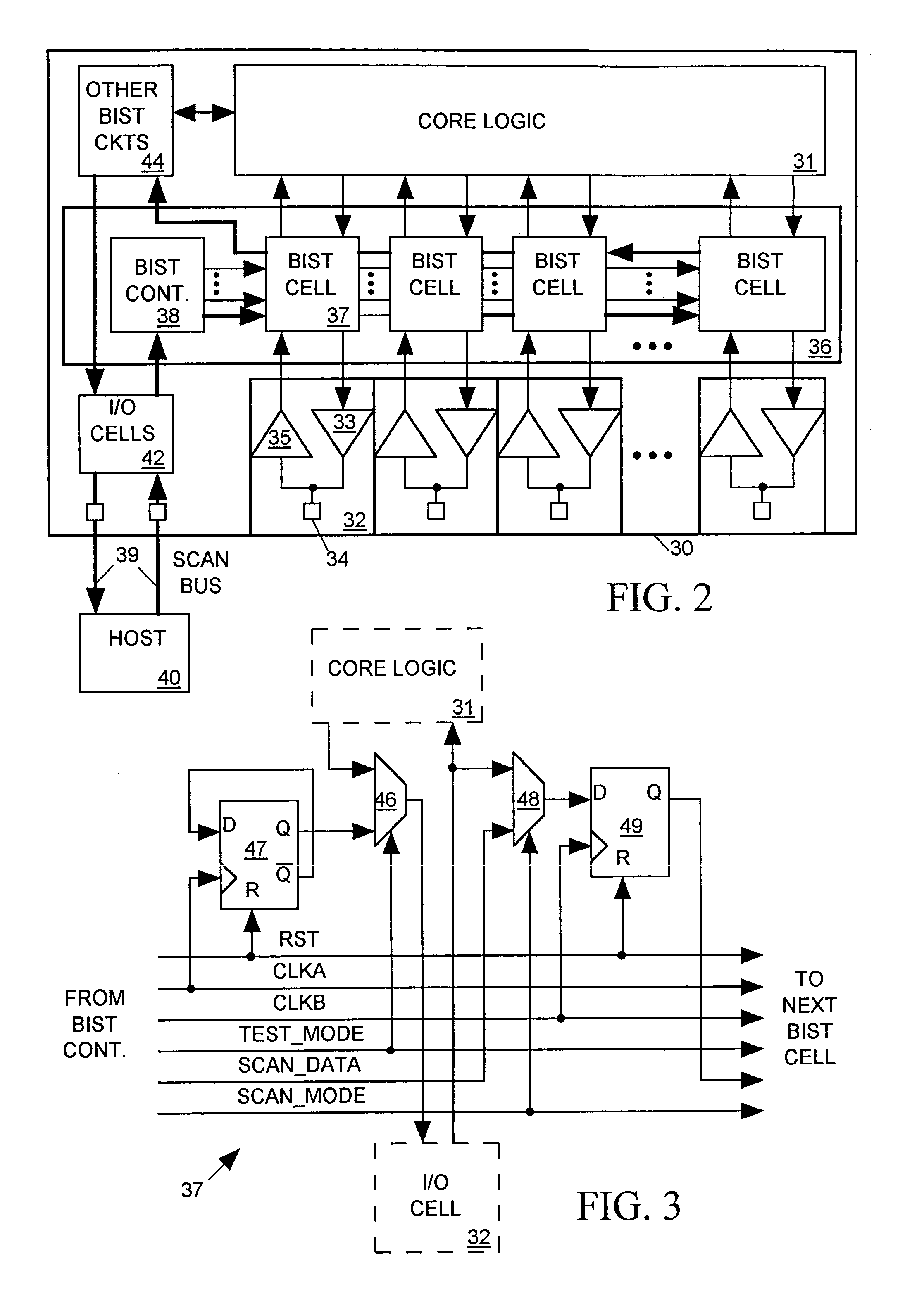
FIG. 2 depicts an IC 30 including core logic 31 for communicating with external circuits through a set of I / O cells 32. Each I / O cell 32 includes a driver 33 for forwarding a signal from core logic 31 outward to the external circuits via a pad 34 on the surface of the IC, and a receiver 35 for forwarding an incoming signal arriving on pad 34 to core logic 31. While an IC designer might like to place timing constraints on driver 33 and receiver 35 specifying path delays through them are to be within some ...


PUM


Abstract

A self-calibrating strobe signal generator for a BIST circuit responds to an edge of an input strobe signal by generating corresponding edges of first and second strobe signals separated in time by a target delay specified by input data. The strobe signal generator includes a multiplexer, a delay circuit and a controller. The multiplexer normally provides the input strobe signal as a multiplexer output signal to the delay circuit which generates edges in each of the first and second strobe signals in response to each edge in the multiplexer output signal with a programmable delay between corresponding first and second strobe signal edges. During a calibration process the control circuit adjusts the programmable delay by counting cycles of a reference clock signal occurring during a predetermined number of cycles of the multiplexer output signal when the multiplexer is set to select the first strobe signal and then the second strobe signal as the source of the multiplexer output signal such that the multiplexer output signal oscillates, and by incrementing or decrementing the programmable delay depending on whether a difference between the counts matches the input data.

Description

BACKGROUND OF THE INVENTION 1. Field of the Invention The present invention relates in general to a self-calibrating strobe signal generator capable of producing edges in two strobe signals with an accurately adjustable delay between them suitable for use in a built-in self-test circuit for measuring path delays in an IC. 2. Description of Related Art IC designers typically place timing constraints on various signal paths within an IC specifying that a state change in a signal path input signal is to produce a state change in a signal path output signal within some specified maximum target delay. Test equipment can test whether the delay between state changes in a signal path's input and output signals is within a such a target delay by changing the state of a signal at the path input and thereafter sampling the signal at the path output with the specified target delay to determine whether the path output signal has changed state. However, in many cases external test equipment c...

Claims


Application Information

Patent Timeline
Patent Type & Authority Applications(United States)
IPC IPC(8): G01R31/3187G01R31/319G01R31/3193H04J3/06
CPCG01R31/3187G01R31/31937G01R31/3191
Inventor FRISCH, ARNOLD M.
Owner CREDENCE SYSTEMS
Why Eureka
Try Eureka