Beam conditioning system

a beam conditioning and beam technology, applied in the field of xray optical systems, can solve the problems of low efficiency, low efficiency, and limited ability of multilayer optics to provide a high capture angle, and achieve the effect of high-flux operations

Active Publication Date: 2005-02-03
OSMIC INC
View PDF14 Cites 19 Cited by
  • Summary
  • Abstract
  • Description
  • Claims
  • Application Information

AI Technical Summary

Problems solved by technology

Although the use of multilayer mirrors in a Kirkpatrick-Baez configuration provides increased efficiency, this type of system is not optimal because mirrors positioned at different distances from the source have different capture angles (i.e., a mirror positioned further from the source has lower efficiency), and, additionally, the beam convergence and image size are different in two planes, resulting in a phenomenon known as anamorphotism.
These applications demand a high flux, but a multilayer optic has limited capabilities to provide a high capture angle because of its relatively large d-spacing.
However, crystals have several drawbacks that have heretofore limited their application in certain x-ray related fields.
Mosaic crystals have a modest reflectivity and a large penetration depth, which is not favorable in applications requiring sharp focusing.
Both types of crystals have a limited acceptance in the axial plane (plane perpendicular to the diffraction plane), and this acceptance drops significantly when an x-ray is not parallel to the diffraction plane.
This last feature makes optical systems with two diffractive elements with small d-spacing and narrow rocking curve ineffective.
These limiting factors have heretofore rendered optics having crystal combinations ineffective in particular x-ray applications.

Method used


Image

  • Beam conditioning system
  • Beam conditioning system
  • Beam conditioning system

Examples


Embodiment Construction

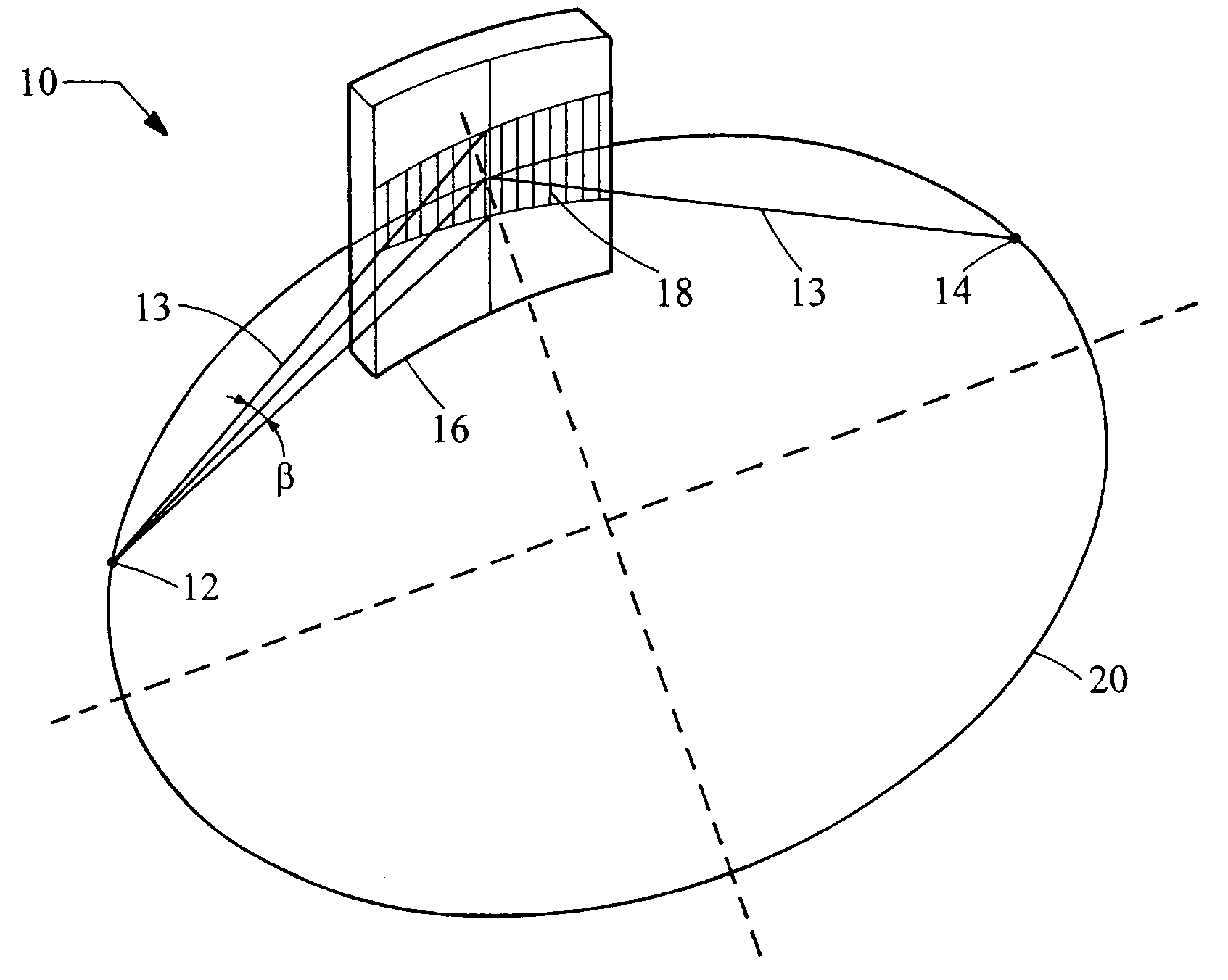
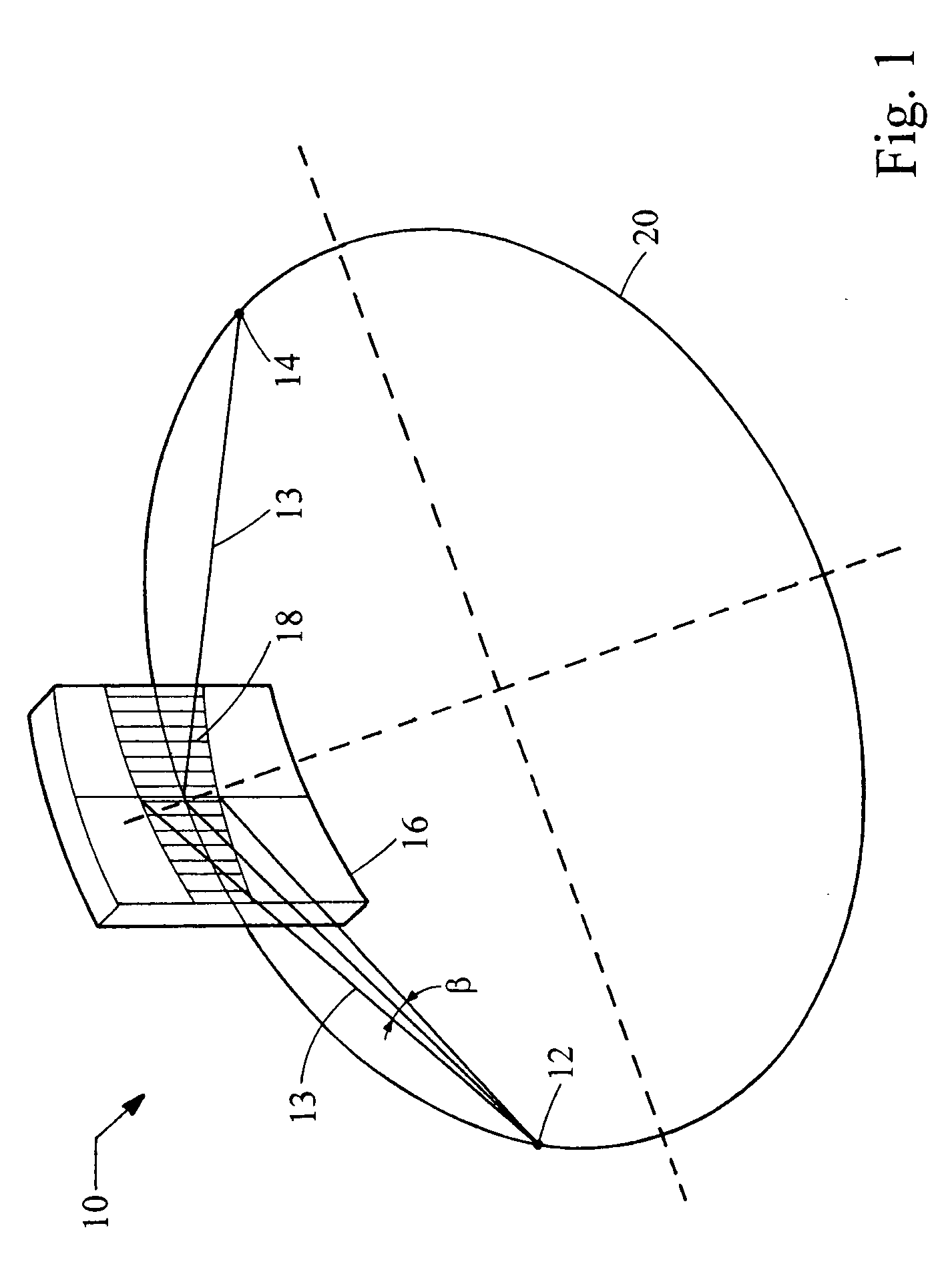
An analysis of the efficiency of various diffractive x-ray optical elements provides a basis for the understanding of the present invention. For simplicity, consider a single diffractive element with a cylindrical reflecting surface and with a capability to focus x-rays from a point source to the point image in the diffraction plane. Examples of such diffractive elements are Johansson crystals and elliptical multilayers with a proper grading of d-spacing. The capability of these optical elements to accept and redirect x-rays from a monochromatic x-ray source can be described as:

ε=f·α·β·R,  (2)

where f is a factor describing from which portion of the source size a diffractive element can use radiation, α and β are the acceptance angles in the diffraction and axial planes, respectively, and R is the element reflectivity.

The efficiency of the source focal spot usage f can be calculated as a convolution of a source spatial intensity distribution and a diffractive element angular ac...


PUM


Abstract

The present invention provides an x-ray beam conditioning system with a Kirkpatrick-Baez diffractive optic including two optical elements, of which one of the optical elements is a crystal. The elements are arranged in a side-by-side configuration. The crystal can be a perfect crystal. One or both diffractive elements can be mosaic crystals. One element can be a multilayer optic. For example, the multilayer optic can be an elliptical mirror or a parabolic mirror with graded d-spacing. The graded d-spacing can be either lateral grading or depth grading, or both.

Description

BACKGROUND The present invention relates generally to an x-ray optical system for conditioning an x-ray beam. More particularly, the present invention relates to a optical system for reflecting an x-ray beam in two directions. There are a number of x-ray applications that require the use of a two dimensional conditioned x-ray beam. For example, medical radiotherapy systems utilize x-ray beams to destroy cancerous tissue, x-ray diffraction or microdiffraction analysis systems channel x-ray radiation at a sample crystal generating a diffraction pattern indicative of a lattice structure, and x-ray fluorescence and spectroscopy systems employ directed and conditioned x-ray beams. A Kirkpatrick-Baez optical configuration has been proposed to reflect an x-ray beam in two directions independently. In the Kirkpatrick-Baez configuration, at least two optical elements are oriented sequentially so that their meridian axes are perpendicular. Using two parabolic optical elements, a Kirkpatric...

Claims


Application Information

Patent Timeline
Patent Type & Authority Applications(United States)
IPC IPC(8): G02B26/08G21K1/06
CPCB82Y10/00G21K1/06G21K2201/064G21K2201/061G21K2201/062G21K1/062
Inventor VERMAN, BORISHARADA, JIMPEI
Owner OSMIC INC
Why Eureka
Try Eureka