
Annuloplasty ring delivery system and method

Inactive Publication Date: 2005-02-03
COSGROVE DELOS M +1
View PDF45 Cites 17 Cited by
  • Summary
  • Abstract
  • Description
  • Claims
  • Application Information

AI Technical Summary

Benefits of technology

[0035] The present invention overcomes the above discussed disadvantages by providing an assembly for holding a substantially flexible suture guide in a substantially taut position for placing a suture line having a predetermined dimension. When attached to the holder assembly, the flexible suture guide assumes a shape or geometry, such as a circumference, that conforms to the shape or geometry of that portion of the body organ or vessel that is being sutured. The holder assembly can be formed to hold the suture guide in any desired shape, whether straight, curvilinear, or a combination of the two and the suture guide can be either biodegradable or permanently implantable. Thus the surgeon undertaking reconstructive surgery is aided in achieving a suture line of any desired shape, geometry and / or dimension.
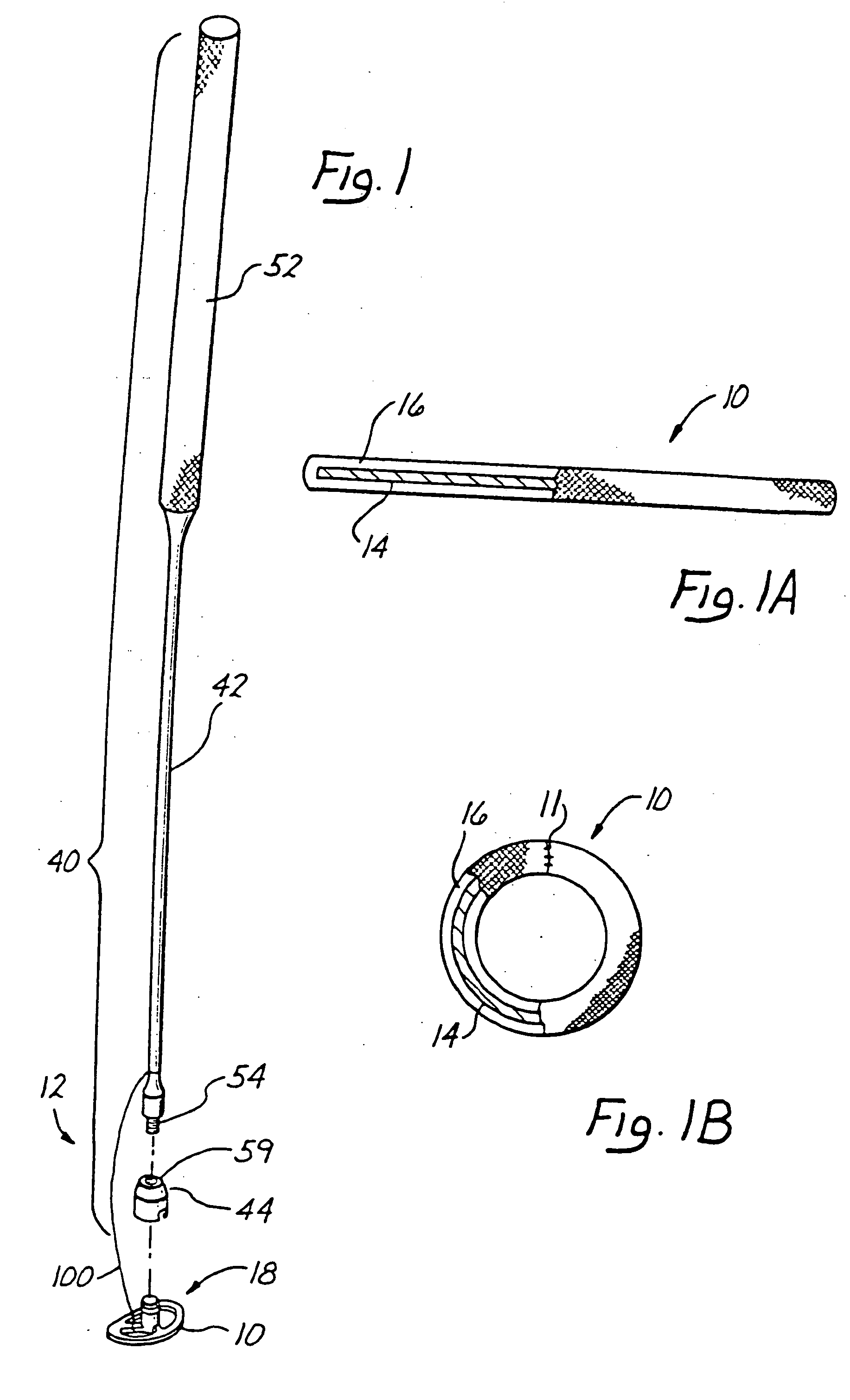
[0037] The flexible suture guide used with the assembly of the invention comprises a generally elongated flexible body element having an internal flexible rib encased within a biocompatible covering, such as a woven cloth material. The suture guide can be formed of either biodegradable or non-biodegradable materials depending upon whether its purpose is to serve as a permanent support to prevent tearing out of the sutures placed through it or whether the suture-supporting function is to be a temporary one. In addition to its function as a post-surgical support for sutures, during surgery when used in combination with the holder disclosed herein, the suture guide serves as a rigid support and template by which the surgeon controls the length of the finished suture line. For instance, if the task is to suture together two ends of a bowel from which a section has been removed, the combination of suture guide and holder assure that the circumference of the surgical jointure is substantially similar to the circumference of the nearby regions of the colon, rather than smaller or larger.
[0038] Therefore, the holder device is designed to lend a temporary rigidity or tautness to the suture guide while lending to it a shape selected to facilitate the suturing task. For instance, when the task is to place a line of sutures around the circumference of a curvilinear surface, the holder is designed to fit around at least a portion of the circumference while holding the suture guide against the said circumference to aid the surgeon in making a surgical jointure that-does not distort the said circumference.

Problems solved by technology

However, sutures often tear through the tissue if they are subjected to stress, thus damaging the surgical closure of the wound.
In many cases, the incision is not a straight line, but is shaped to conform to an anatomical requirement, making it difficult for the surgeon to balance the tension on the sutures to form the desired shape.
Similar problems arise during bowel and bronchial resection.
Diseases and certain natural defects to heart valves can impair the functioning of the cusps of the valves in preventing regurgitation of blood from the ventricle into the atrium when the ventricle contracts.
For example, rheumatic fever and bacterial inflammations of the heart tissue can distort or dilate the valvular annulus, thus resulting in displacement of the cusps away from the center of the valve and causing leakage of blood during ventricle contraction.
Since a normal heart valve annulus continuously flexes during the cardiac cycle, a rigid ring prosthesis interferes with this movement and thereby restricts movement of the valve itself.
However, completely flexible ring prostheses provide almost no support to the suture area during the precarious implant procedure.
But due to rigidity of the frame members, the self-adjusting prostheses do not overcome many of the disadvantages of other types of rigid ring prostheses.
While rigid and semi-rigid annuloplasty rings eliminate the bunching caused by flexible rings, the restrictive nature of such rings is generally detrimental to the valve's ability to open and close normally.
However, an entirely flexible suture guide cannot prevent bunching of the tissue in the draw-string effect described above and thus cannot assure that the suture line and the tissue into which it is placed will maintain any desired dimension, for example, a desired circumference.

Method used


Image

  • Annuloplasty ring delivery system and method
  • Annuloplasty ring delivery system and method
  • Annuloplasty ring delivery system and method

Examples


Embodiment Construction

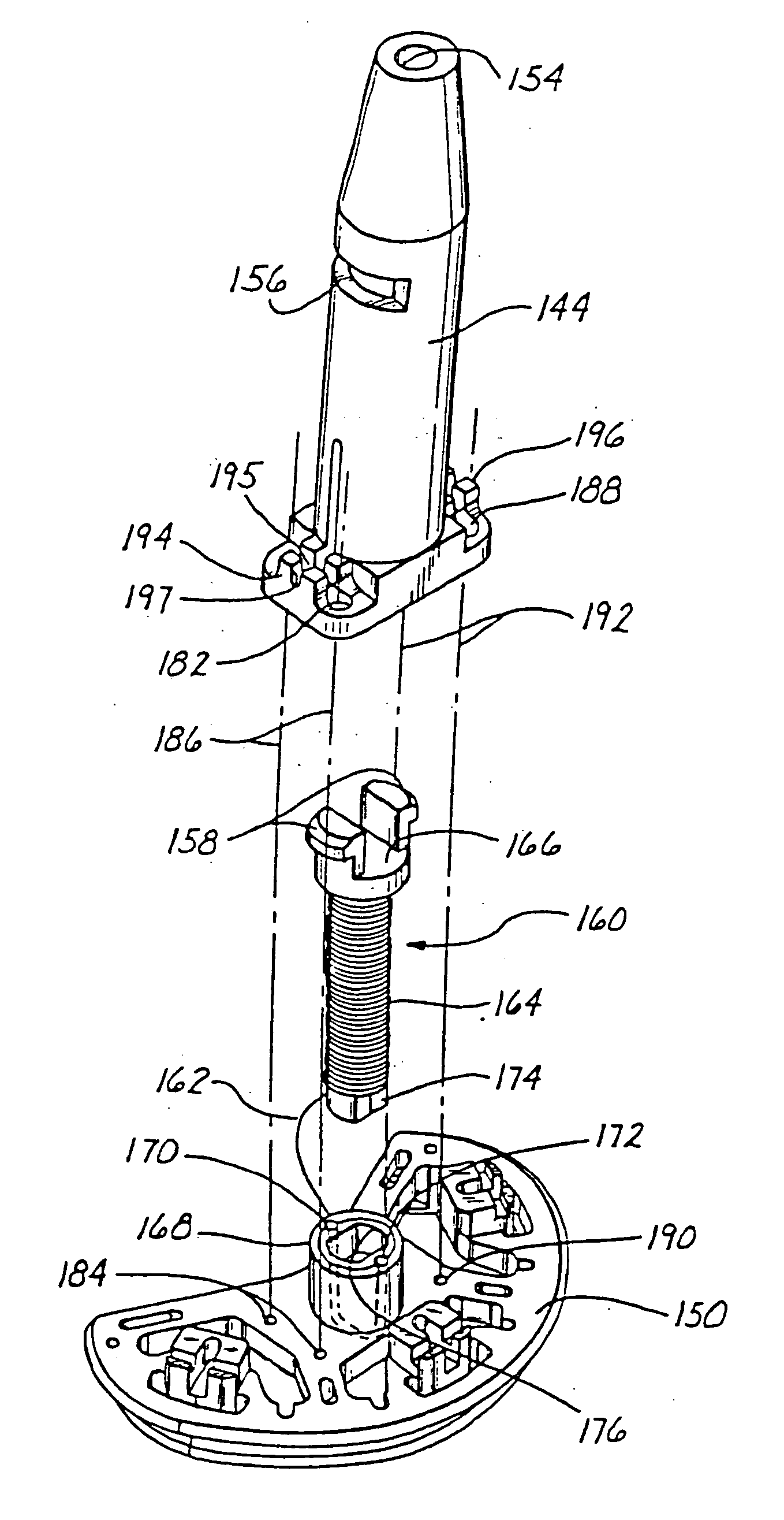
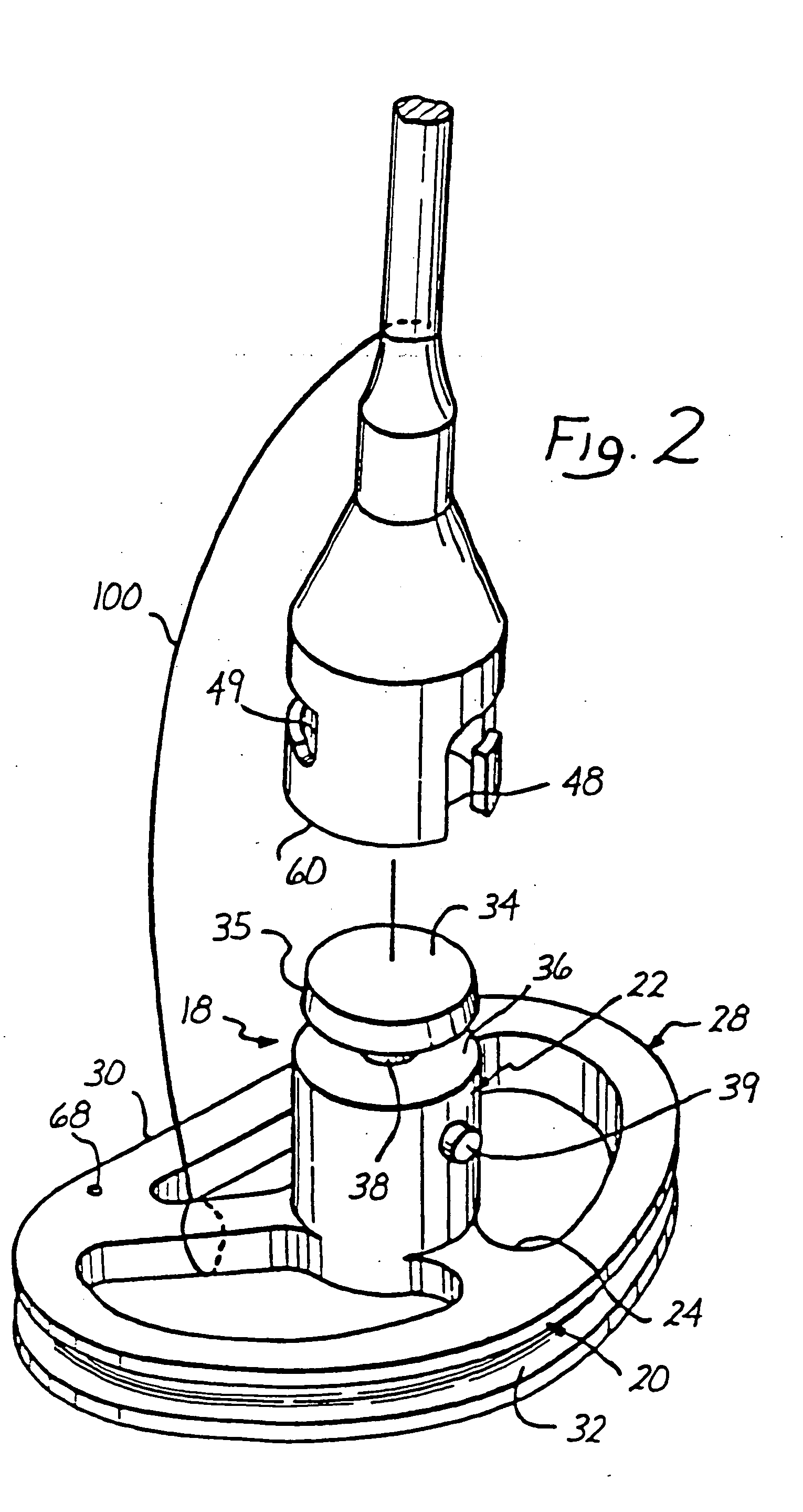
[0041] The present invention is directed to a holder assembly for holding a substantially flexible, implantable suture guide in a substantially taut position for suturing along a suture line having a desired shape or dimension, such as the desired circumference to which an enlarged heart valve annulus is to be reduced by the formation of pleats about the base of the valve annulus. The suture guide of the invention is formed from a freely flexible rib encased within a woven cloth covering. In use, the flexible suture guide of the invention is held taut by the holder assembly and in a configuration determined by the shape of the holder assembly while the surgeon uses the support provided by the taut suture guide to evenly place the sutures and to draw the tissue by means of the sutures passed through the suture guide into a suture line having a shape substantially similar to that of the suture guide and holder. For example, for use in annuloplasty, the holder assembly can be C-shaped ...


PUM


Abstract

An assembly for holding a substantially flexible suture guide of predetermined length in a substantially taut position used to achieve a suture line having a dimension equal to the length of the suture guide, such as the circumference about a heart valve annulus. The assembly includes a rigid suture guide holder having a surface against which the length of suture guide is releasably positioned. The guide holder can have a shape or geometry, such as a circumference or circumferential segment, equivalent to the shape or geometry of the intended suture line. The shape of the guide holder can therefore be selected to hold the suture guide in the shape most advantageous to placing the desired suture line. The assembly further includes a mechanism for releasably binding the suture guide to the surface of the holder and a detachable handle extendibly attached to the holder by means of a lanyard so that the handle can be detached to afford an unobstructed view of the surgical site, but cannot be removed from the surgical site until the holder has also been removed.

Description

RELATED APPLICATIONS [0001] This application is a continuation-in-part of co-pending U.S. patent application Ser. No. 387,909, filed on Jul. 31, 1989 and Ser. No. 444,189 filed on Nov. 30, 1989. The present invention relates to a surgical suture guide used to control the dimension and / or shape of a suture line placed during surgical repair of an organ or body part. In particular, the present invention relates to a combination of a flexible suture guide releasably attached to a rigid holder for controlling the spacing and placement of surgical sutures.BACKGROUND OF THE INVENTION [0002] During surgical repair of an organ or other body part, the surgeon typically makes an incision to open the organ. Upon closure of the surgical wound, sutures are placed in the various layers of tissue to draw the two edges of the wound together so that the healing process can reform a smooth and competent surface. However, sutures often tear through the tissue if they are subjected to stress, thus dama...

Claims


Application Information

Patent Timeline
IPC IPC(8): A61B17/04A61B19/00A61B19/02A61F2/24
CPCA61B17/0482A61B19/00A61B19/0256A61F2/2427Y10S623/904A61F2/2448A61F2/2466Y10S623/90A61F2/2445A61B90/00A61B50/20
Inventor COSGROVE, DELOS M.NGUYEN, THAN
Owner COSGROVE DELOS M
Learn More