Variable compression ratio mechanism

a compression ratio and variable technology, applied in the direction of auxillary lubrication, electric control, combustion engines, etc., to achieve the effect of large acceleration and fine control of the amount of movemen

Active Publication Date: 2005-02-10
TOYOTA JIDOSHA KK
View PDF2 Cites 9 Cited by
  • Summary
  • Abstract
  • Description
  • Claims
  • Application Information

AI Technical Summary

Benefits of technology

[0040] In this connection, though all of the camshafts and the bearing portions can be formed into tapered configurations, only those parts of them which are liable to be subjected to loads resulting from the self weight of the cylinder block, combustion pressure, etc., may be formed into tapered configurations. In this case, it is possible not only to solve the problem of the present invention of suppressing a shortage of oil films between the camshafts and the bearing portions but also to suppress an increase in the manufacturing man hours of the camshafts to a minimum.
[0041] As a concrete method of driving the camshafts to axially move back and forth, there may be adopted a method in which, similar to the above-mentioned cases, a pair of objects each having an appropriate mass are arranged at the opposite ends, respectively, of each camshaft to be moved back and forth, so that the objects are provided with inertia and forced to strike or collide against each corresponding camshaft from the axial direction thereof by momentarily impressing a voltage on actuators such as piezo-electric elements or the like which act to apply impacts to the objects, respectively. This method is particularly effective in the case of moving objects under friction such as the camshafts in the present invention, and is able to perform fine control on the amount of movement of each camshaft.
[0042] Further, loads such as the self weight of the cylinder block, combustion or firing pressure in the cylinders, etc., are applied to between the camshafts and the bearing portions, as previously stated. Accordingly, when the camshafts are caused to move axially in a direction to increase the diameters of their tapered portions, the cylinder block, etc., moves in a direction substantially perpendicular to the axial detection of the camshafts (i.e., a direction not to increase or expand the gaps or clearances between the camshafts and the bearing portions) so as to follow the movements of the camshafts. In contrast to this, as a method of moving the camshafts in the axial direction, there may be adopted a method in which objects are provided with inertia and forced to strike or collide against the camshafts from the axial direction thereof by momentarily impressing a voltage on actuators such as piezo-electric elements, etc. In this case, the camshafts can be driven to move at a large acceleration. As a consequence, the gaps or clearances between the camshafts and the bearing portions can be increased or expanded to a satisfactory extent while overcoming the motion of the cylinder block, etc., which prevents widening or expansion of the gaps or clearances between the camshafts and the bearing portions.
[0043] As another method capable of forcing the camshafts to move back and forth at a large acceleration, there may be adopted a method in which a pair of cams for back-and-forth movement are separately arranged at the opposite ends of each camshaft, and the cams for back-and-forth movement are driven to rotate at high speed so that they are caused to strike or collide against the opposite ends of each corresponding camshaft.
[0044] Furthermore, though the camshafts, when driven to move in the direction to increase the diameters of their tapered portions, can be moved at a large acceleration, a particularly large acceleration is not required in the movements of the camshafts when they are returned to their original positions. Therefore, as a concrete method for returning the camshafts to their original positions, there may be employed, other than the above-mentioned ones, a method utilizing repulsive forces produced by electromagnets or a method utilizing the resilient forces of springs or the like so as to return the camshafts to their own their positions.
[0045] Preferably, the distance of the back-and-forth movement in this method, though determined by the relation thereof with the tapered configurations, may be in the range of from about several tens μm to about several hundreds μm. In addition, the number of back-and-forth movements is not limited to one time, but may be a plurality of times.

Problems solved by technology

In addition, the camshafts in the above-mentioned prior art are not driven to rotate at high speed and at all times during engine operation as the camshafts in the crankshafts or the valve systems.

Method used


Image

  • Variable compression ratio mechanism
  • Variable compression ratio mechanism
  • Variable compression ratio mechanism

Examples


embodiment 1

[0084] [Embodiment 1]

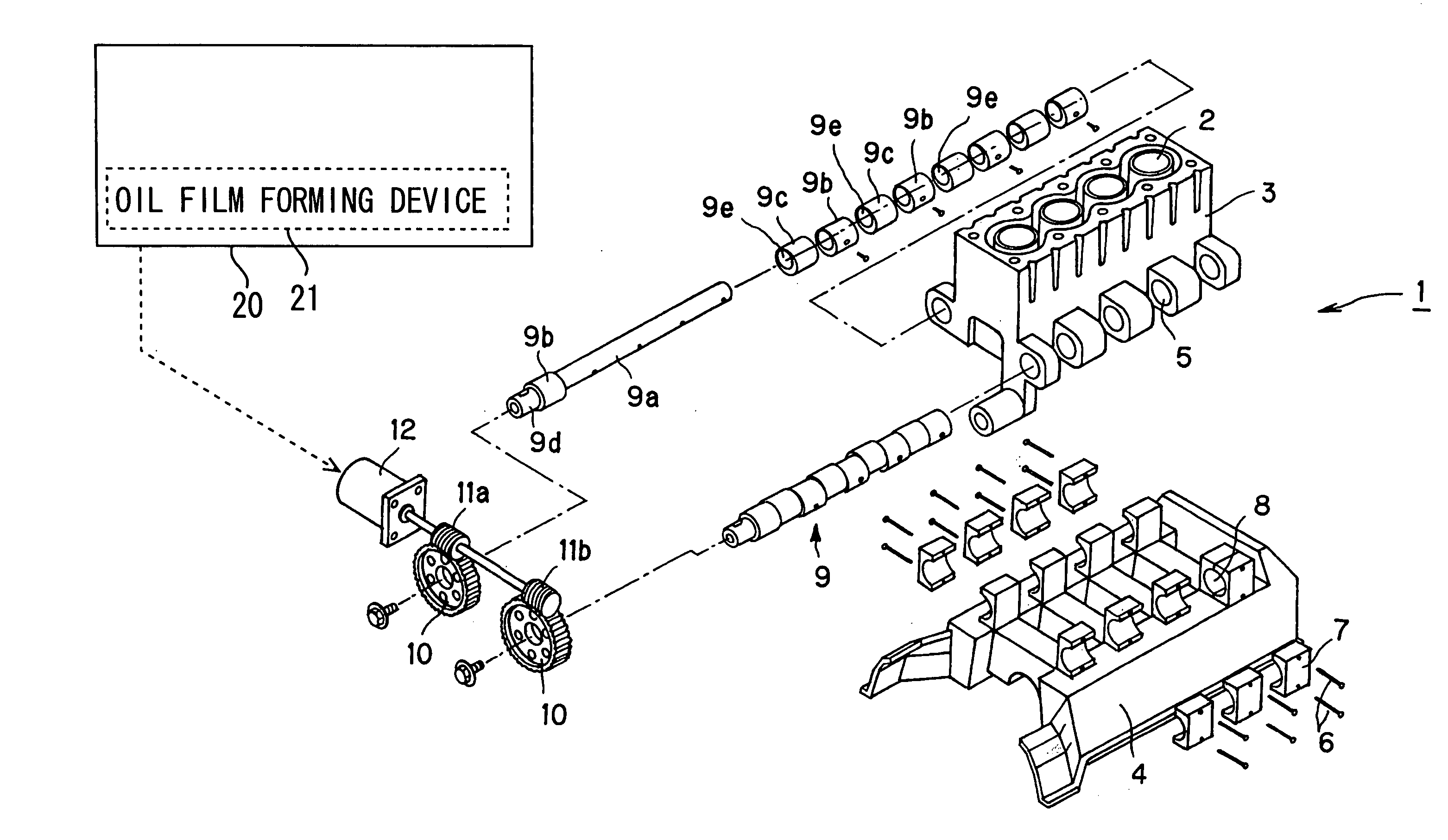
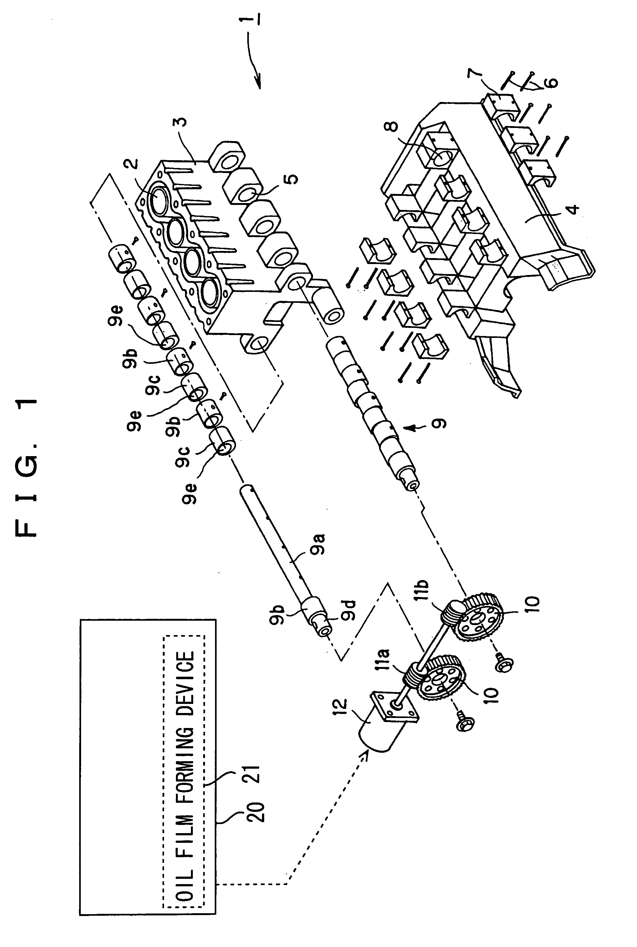
[0085] An internal combustion engine, which is generally designated at reference numeral 1 and will be described below, is a variable compression ratio type internal combustion engine whose compression ratio is changed by moving a cylinder block 3 with a plurality of cylinders 2 relative to a crankcase 4 coupled with unillustrated pistons in the axial direction of the cylinders.

[0086] First of all, reference will be made to the construction of the variable compression ratio type internal combustion engine according to a first embodiment of the present invention by using FIG. 1. As shown in FIG. 1, the cylinder block 3 has a plurality of projected portions formed at the lower opposite sides thereof, with a cam receiving hole 5 being formed in each of the projected portions. Each of the cam receiving holes 5 takes a circular or round shape in cross section, and they are formed in such a manner that they are disposed substantially perpendicular to the axial direct...

embodiment 2

[0113] [Embodiment 2]

[0114] Now, a second embodiment of the present invention will be described below. Herein, only those portions of this embodiment which are different from the above-mentioned first embodiment will be described, with the same portions in these embodiments being identified by the same reference symbols while omitting an explanation thereon.

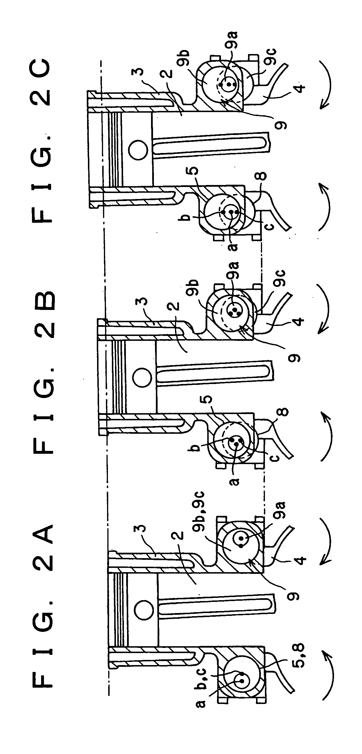
[0115] In the above-mentioned first embodiment, there has been explained the case in which when the camshafts 9 are started to rotate or are being rotated so as to change the combustion ratio of the internal combustion engine 1, oil films are formed between the camshafts 9 and the bearing portions 18 by rotating the camshafts 9 in a reciprocating manner. However, in this second embodiment, reference will be made to the case where the reciprocating rotation of the camshafts 9 as explained in the first embodiment is performed at the time when the camshafts 9 are stopped, i.e., at times other than the time of changing the compressi...

embodiment 3

[0129] [Embodiment 3]

[0130] Next, a third embodiment of the present invention will be described below. Herein, only those portions of this embodiment which are different from the above-mentioned first embodiment will be described, with the same portions in these embodiments being identified by the same reference symbols while omitting an explanation thereon.

[0131] In the above-mentioned first and second embodiments, there has been explained the case in which oil films are formed between the camshafts 9 and the bearing portions 18 by rotating the camshafts 9 in a reciprocating manner, but in this third embodiment, reference is made to the case where spaces or clearances between the camshafts 9 and the corresponding bearing portions 18 are formed into tapered shapes or configurations, so that oil films are formed between the camshafts 9 and the corresponding bearing portions 18, which are formed into tapered configurations, by axially moving the camshafts 9 back and forth relative to...


PUM


Abstract

In a variable compression ratio mechanism that serves to change the compression ratio of an internal combustion engine by rotating camshafts so as to cause relative movement between a cylinder block and a crankcase, an oil film forming device forms oil films on the sliding portions of camshafts.

Description

BACKGROUND OF THE INVENTION [0001] 1. Field of the Invention [0002] The present invention relates to a variable compression ratio mechanism capable of changing the compression ratio of an internal combustion engine by changing the volume of each combustion chamber thereof. [0003] 2. Description of the Related Art [0004] In recent years, there have been proposed techniques capable of changing the compression ratio of an internal combustion engine for the purpose of improving fuel mileage performance, output performance, etc. As such kinds of techniques, there has been proposed one in which a cylinder block and a crankcase are coupled with each other, and camshafts are mounted on the coupling portions thereof, respectively, in such a manner that the compression ratio of the engine is changed by rotating the camshafts so as to move the cylinder block and the crankcase toward and away from each other (for example, see a first patent document: Japanese patent application laid-open No. 20...

Claims


Application Information

Patent Timeline
Patent Type & Authority Applications(United States)
IPC IPC(8): F01M1/16F01M9/10F02B75/04F02D15/04F02D45/00
CPCF02B75/047F02B75/041
Inventor AKIHISA, DAISUKEKAMIYAMA, EIICHI
Owner TOYOTA JIDOSHA KK
Why Eureka
Try Eureka