Annealing-induced extensive solid-state amorphization in metallic films

Inactive Publication Date: 2005-02-10
NATIONAL TAIWAN OCEAN UNIVERSITY
View PDF5 Cites 14 Cited by
  • Summary
  • Abstract
  • Description
  • Claims
  • Application Information

AI Technical Summary

Benefits of technology

Accordingly, the purpose of this invention is to produce an alloy film based on elements with high glass-forming ability with extensive amorphous s

Problems solved by technology

In all these solid-state techniques except for the SSA, considerable energy is generally required for ultimate amorphization.
Though the above-mentioned solid-state technique can successfully synthesize bulk amorphous alloys, it is apparent that the machining-involved technique is not suitable for films formation and the use of SSA in film formations is limited.
However, the extent of amorphization in this case is trivial and confined to the reacted interface with the thickness of few nanometers, as shown by B. X. Liu, W. S. Lai and z. J. Zhang (“Solid-State Crystal-to-Amorphous Transition in Metal-Metal Multilayers and Its Thermodynamic and atomistic Modeling” Adv.
It is due to that the elemental components of traditional deposition and sputter systems are not necessarily the same with BMG and there are substantial differences between the film and bulk manufacturi

Method used


Image

  • Annealing-induced extensive solid-state amorphization in metallic films
  • Annealing-induced extensive solid-state amorphization in metallic films
  • Annealing-induced extensive solid-state amorphization in metallic films

Examples


example 1

Zr-based thin film

Experimental Procedure

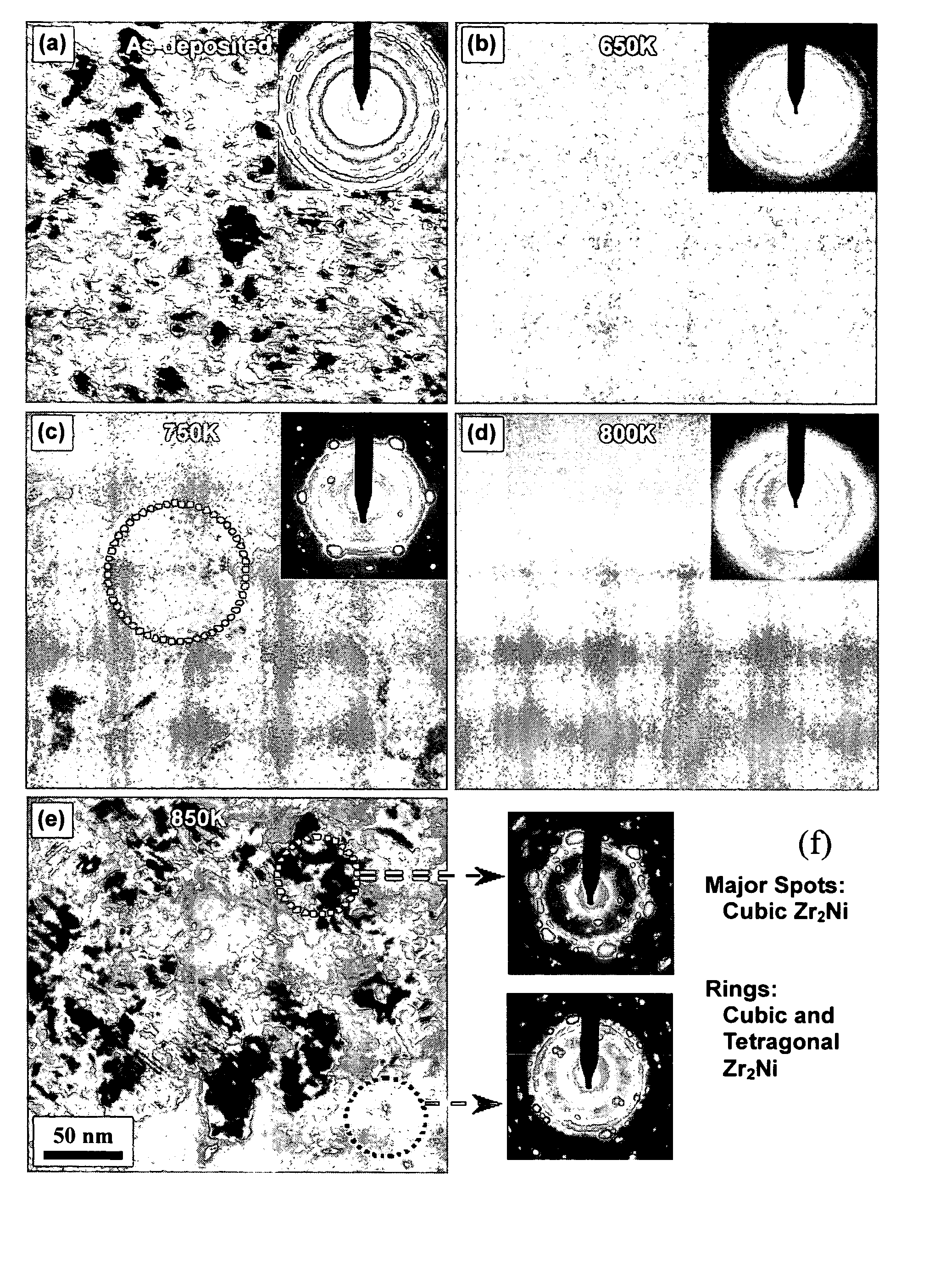
Zr-based quaternary alloy thin films of thickness 5-10 μm with a nominal composition of Zr47Cu31Al13Ni9 were deposited onto the well-cleaned glass substrate using an RF magnetron sputtering system in an argon atmosphere. The working pressure and RF power during sputtering were maintained at 3×10⁻³ torr and 100 W, respectively. The compositions of the films were measured using an electron probe for microanalysis (EPMA). The compositional fluctuation at various points on the film surface was also determined and found to be very small, (around 1%) which reveals the uniformity of the deposited films. The films were then annealed in a rapid thermal annealing (RTA) system in Ar at temperatures ranging from 550 to 950 K. To avoid contamination, the RTA system was pumped down to 10−3 torr range followed by purging with pure Ar for several times. For RTA, the samples were kept 60 seconds in holding time with the heating rate of 40 K / min. The crysta...

example 2

Fe-based thin films

Experimental procedure

The Fe65CO8Ni7T13Nb1B6 (atomic percent, at. %) thin films were prepared by anRF magnetron sputtering method. The Fe-Co-Ni-Ti-Nb-B target was an as-cast alloy. Thin films of thickness 0.5-10 μm were deposited on glass substrate. The deposition was carried out under the following conditions. The base vacuum was 10−7 Torr, Ar gas flow rate was 20 sccm, and the working pressure was 3×10⁻³ Torr. The power of 100 W was applied during the deposition. The film was annealed in Ar at a heating rate of 100 K / min and a holding time of 60 s at temperatures ranging from 673 to 1073 K. The annealing system was pumped down to the 10−3 Torr range followed by several purging with Ar. Compositions of thin films were determined by Electron Probe Microanalyzer. The thermal behavior of the film was determined using a differential scanning calorimeter (DSC) in Ar at a scanning rate of 100 K / min. The DSC film sample was delaminated from the glass without the aid...


PUM

PropertyMeasurementUnit
Temperatureaaaaaaaaaa
Fractionaaaaaaaaaa
Fractionaaaaaaaaaa

Abstract

An thin film alloy based on chemical elements with high glass forming ability is disclosed. The alloy is deposited as a thin film from a source of substantially the same chemical composition. Within the deposited thin film, amorphization is induced extensively up to decades of micrometers in size during controlled annealing. Such controllable extensive amorphization throughout the thin film is useful to regulate the proportion of amorphous phase to crystalline phase, establish the structure/property relationships and thus tailor specific properties.

Description

BACKGROUND OF THE INVENTION 1. Field of the Invention The present invention relates to an alloy film and a process for manufacturing the same, especially to an annealing-induced alloy film and a process for manufacturing the same. 2. Description of the Related Art Bulk metallic glass (BMG), also called bulk amorphous metal (BAM) or bulk amorphous alloy (BAA), is a new material with distinctive properties for special use. As compared with the traditional amorphous metals formed from melting state rapidly, this material has higher glass-forming ability (GFA). It can be made into amorphous bulk form at extremely low cooling rates and its thermal stability is better than that of the crystalline metals. For example, A. L. Greer (“Metallic Glasses”, Science, 267, 1947(1995)), A. Inoue (“Stabilization of Metallic Supercooled Liquid and Bulk Amorphous Alloys”, Acta Mater., 48, 279(2000)) and Y Zhang, D. Q. Ahao, M. X. Pan and W. H. Wang (“Glass Forming Properties of Zr-based Bulk Amorph...

Claims


Application Information

Patent Timeline
IPC IPC(8): C22C45/00C22F1/00
CPCC22C45/00
Inventor CHU, JINN P.KUO, CHUN-HSINLO, CHANG-TING
Owner NATIONAL TAIWAN OCEAN UNIVERSITY
Why Eureka
Try Eureka