Detachable substrate or detachable structure and method for the production thereof

a technology of detachable substrates and substrates, applied in the direction of lamination, decorative surface effects, decorative arts, etc., can solve the problems of excessive cost of substrates that are beneficial for the production of components, a posteriori bulky substrates used to produce epitaxial stacks, and insufficient availability of highly resistive substrates at the same cost. , to achieve the effect of reducing the risk of untimely delamination

Inactive Publication Date: 2005-02-10
COMMISSARIAT A LENERGIE ATOMIQUE ET AUX ENERGIES ALTERNATIVES
View PDF62 Cites 131 Cited by
  • Summary
  • Abstract
  • Description
  • Claims
  • Application Information

AI Technical Summary

Benefits of technology

[0033] Accordingly, the interface or intermediate layer produced between the thin layer and the substrate is mechanically weaker in its central portion that at its periphery. This greatly reduces the risk of untimely delamination.

Problems solved by technology

Another object relates to the fact that in this particular example the sapphire substrate used to produce the epitaxial stack is a posteriori bulky, in particular because it is electrically insulative, which prevents making electrical contacts to its rear face.
However, a highly resistive substrate is not necessarily available at the same cost and with the same quality as the standard substrates usually employed.
There may also be cited situations in which the substrate that is beneficial for the production of the components is excessively costly.
In some cases the transfer to another support is not indispensable, especially if the final thickness aimed at during thinning is sufficient to produce self-supporting structures.
These techniques are of great benefit since they enable a layer to be transferred from one substrate to another, but they necessarily consume the basic substrate (which is destroyed during the process) and cannot achieve homogeneous transfer of a thin film unless a stop layer is present (i.e. a non-homogeneous layer in the substrate material).
Unfortunately, the fracture is difficult to control and necessitates high mechanical stresses to bring it about, which is not free of the risk of breaking of the substrate or damaging the components.

Method used


Image

  • Detachable substrate or detachable structure and method for the production thereof
  • Detachable substrate or detachable structure and method for the production thereof
  • Detachable substrate or detachable structure and method for the production thereof

Examples


Embodiment Construction

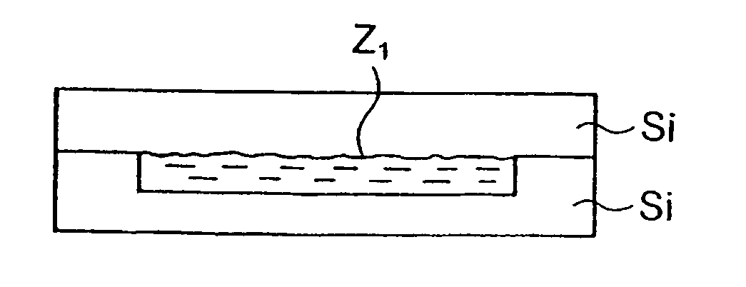
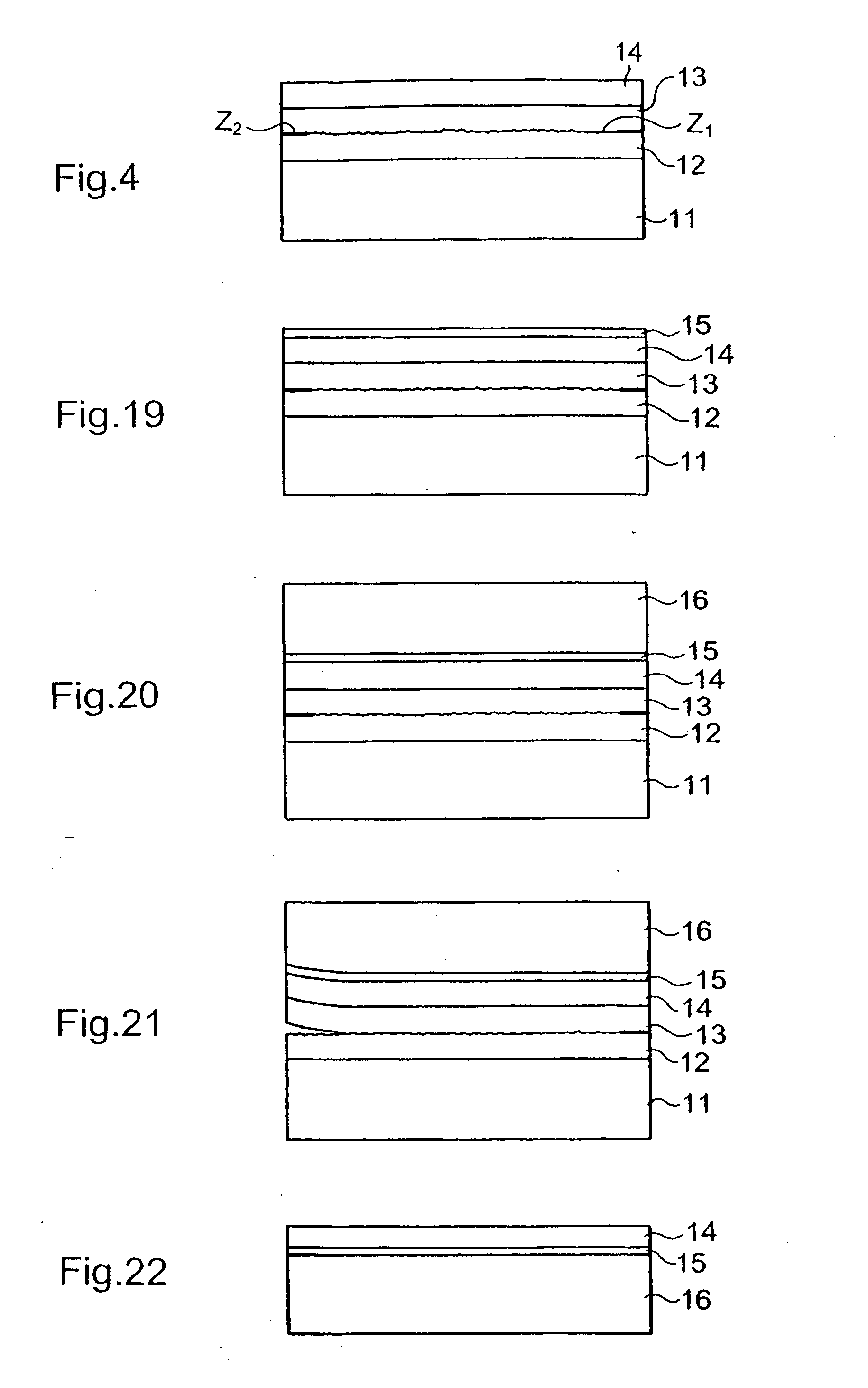
[0118] 1—Molecular Adhesion Bonding Interface

[0119] The preferred examples selected for the detailed description primarily relate to silicon, which is generally available in the form of round substrates, for example of 200 mm diameter. These methods transfer readily to other systems characterized in particular by materials other than silicon, in a nonlimiting manner and without departing from the scope of the invention.

[0120] Some embodiments of the method according to the invention tend to encourage lifting of the layer off its substrate at the overall level, i.e. on the scale of the whole of the substrate, while others tend to delimit fragments.

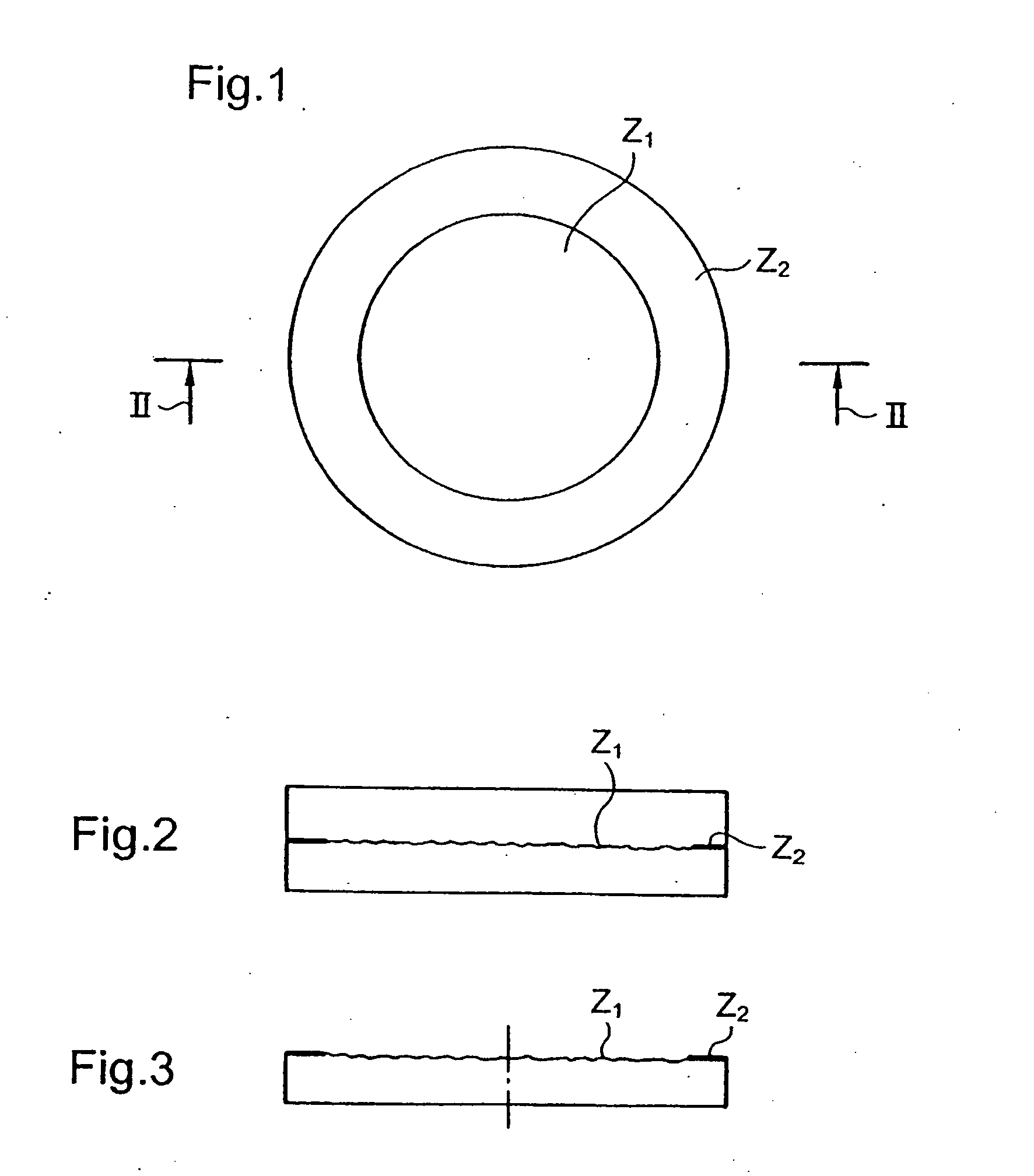
[0121] An assembly to be produced in the former case is shown diagrammatically in FIGS. 1 and 2, the interface or intermediate layer shown diagrammatically in FIG. 2 representing the region in which local bonding differences are to be created. In addition to these figures, FIG. 3 in particular shows one example of the preparation of a su...


PUM

PropertyMeasurementUnit
sizeaaaaaaaaaa
sizeaaaaaaaaaa
thicknessesaaaaaaaaaa

Abstract

The invention relates to the preparation of a thin layer comprising a step in which an interface is created between a layer used to create said thin layer and a substrate, characterized in that said interface is made in such way that it is provided with at least one first zone (Z1) which has a first level of mechanical strength, and a second zone (Z2) which has a level of mechanical strength which is substantially lower than that of the first zone. Said interface can be created by glueing surfaces which are prepared in a differentiated manner, by a layer which is buried and embrittled in a differentiated manner in said zones, or by an intermediate porous layer.

Description

FIELD OF THE INVENTION [0001] The invention relates to the production of components from a thin layer on a substrate and the production of this thin layer / substrate assembly. The substrate can be an initial or intermediate substrate and can be detachable, i.e. adapted to be separated from the thin layer. DESCRIPTION OF THE PRIOR ART [0002] Increasingly, components must be integrated onto supports different from those used to produce them. [0003] Components on plastics material substrates or on flexible substrates may be cited, for example. By component is meant any microelectronic, opto-electronic or sensor (for example chemical, mechanical, thermal, biological or biochemical sensor) device that is completely or partly “processed”, i.e. completely or partly produced. [0004] A layer transfer method can be used to integrate the components onto flexible supports. [0005] There are many other examples of applications in which layer transfer techniques can provide a suitable solution for ...

Claims


Application Information

Patent Timeline
Patent Type & Authority Applications(United States)
IPC IPC(8): H01L21/02H01L21/68H01L21/762H01L21/78H01L27/12
CPCH01L21/6835H01L21/76254H01L21/76259H01L21/7813Y10T156/11H01L2221/68363H01L2924/19041H01L2221/68318H01L2221/68359H01L29/84
Inventor ASPAR, BERNARDMORICEAU, HUBERTZUSSY, MARCRAYSSAC, OLIVIER
Owner COMMISSARIAT A LENERGIE ATOMIQUE ET AUX ENERGIES ALTERNATIVES
Why Eureka
Try Eureka