
Vehicle behavior control device

Active Publication Date: 2005-02-10
TOYOTA JIDOSHA KK
View PDF10 Cites 19 Cited by
  • Summary
  • Abstract
  • Description
  • Claims
  • Application Information

AI Technical Summary

Benefits of technology

It is one object of the present invention to provide a vehicle behavior control device employing a novel control strategy, suppressing deterioration of a vehicle behavior which would be induced during behavior control processes. The vehicle to be equipped with the control device has wheels, a braking system including braking force generating apparatuses for the respective wheels. The inventive control strategy is useful especially for correcting or inhibiting excessive deterioration of a vehicle behavior such as when a risk of rolling-over is detected.
As described above, in conventional behavior control device, while a target value itself is appropriately determined (using a certain theory of motion of a turning vehicle), an increment and / or a decrement of braking force for adjusting actually generated barking force value to its target value are not strictly regulated. The increment and / or decrement of braking force, if they are too large, would change an attitude of a vehicle body excessively, often inducing rolling and / or pitching oscillations and other behavior deterioration on a vehicle body during transition of braking force values or slip ratios toward their targets. When a target value is rather high such as when a risk of rolling-over of a vehicle is detected, these phenomena due to a rather large control amount are more possible. If rolling and / or pitching oscillations are increased, a risk of rolling-over could not be reduced.
In the inventive device, a target braking control amount for reducing a possibility of rolling-over a vehicle may be determined based upon a control parameter for stabilizing a vehicle behavior. Thus, the target braking control amount will be increased by increasing the behavior stabilizing control parameter. Since a possibility of rolling-over would be large upon unusually abrupt steering and / or excessive turning of a vehicle, the target braking control amount may be a target braking force value on a turning outside front wheel. The increase in the braking force on a turning outside front wheel generates anti-spin yaw moment (yaw moment in the direction opposite to the turning direction), which will reduce a yaw rate increased in the turning direction due to the abrupt and / or excessive turning, thereby suppressing the increase of the lateral force on the vehicle body in the turning outside direction (the centrifugal force) and reducing the possibility of rolling-over. More specifically, the target braking control amount may be a target slip ratio of a wheel, and the increasing and decreasing gradients of braking force on the turning outside front wheel will be restricted.
A possibility or a risk of rolling-over may be detected based upon driving operation of a driver of the vehicle, using a steering angle and a steering speed as parameters, although such a risk may be also detected based upon vehicle behavioral condition such as a yaw rate, a lateral deceleration and vehicle speed. Rather, the detection based upon the driving operation advantageously allows starting the control for reducing a risk of rolling-over in advance, namely before a behavior has been highly deteriorated (Driving operation is considered as the input of a system of a vehicle behavior. The actual behavior variation, the response to the input, delays from the input.). Because of such advanced starting of the control, a target braking control amount can be set large enough to correct a behavior for reducing a risk of rolling-over.

Problems solved by technology

The increment and / or decrement of braking force, if they are too large, would change an attitude of a vehicle body excessively, often inducing rolling and / or pitching oscillations and other behavior deterioration on a vehicle body during transition of braking force values or slip ratios toward their targets.

Method used


Image

  • Vehicle behavior control device
  • Vehicle behavior control device
  • Vehicle behavior control device

Examples


Embodiment Construction

Vehicle System

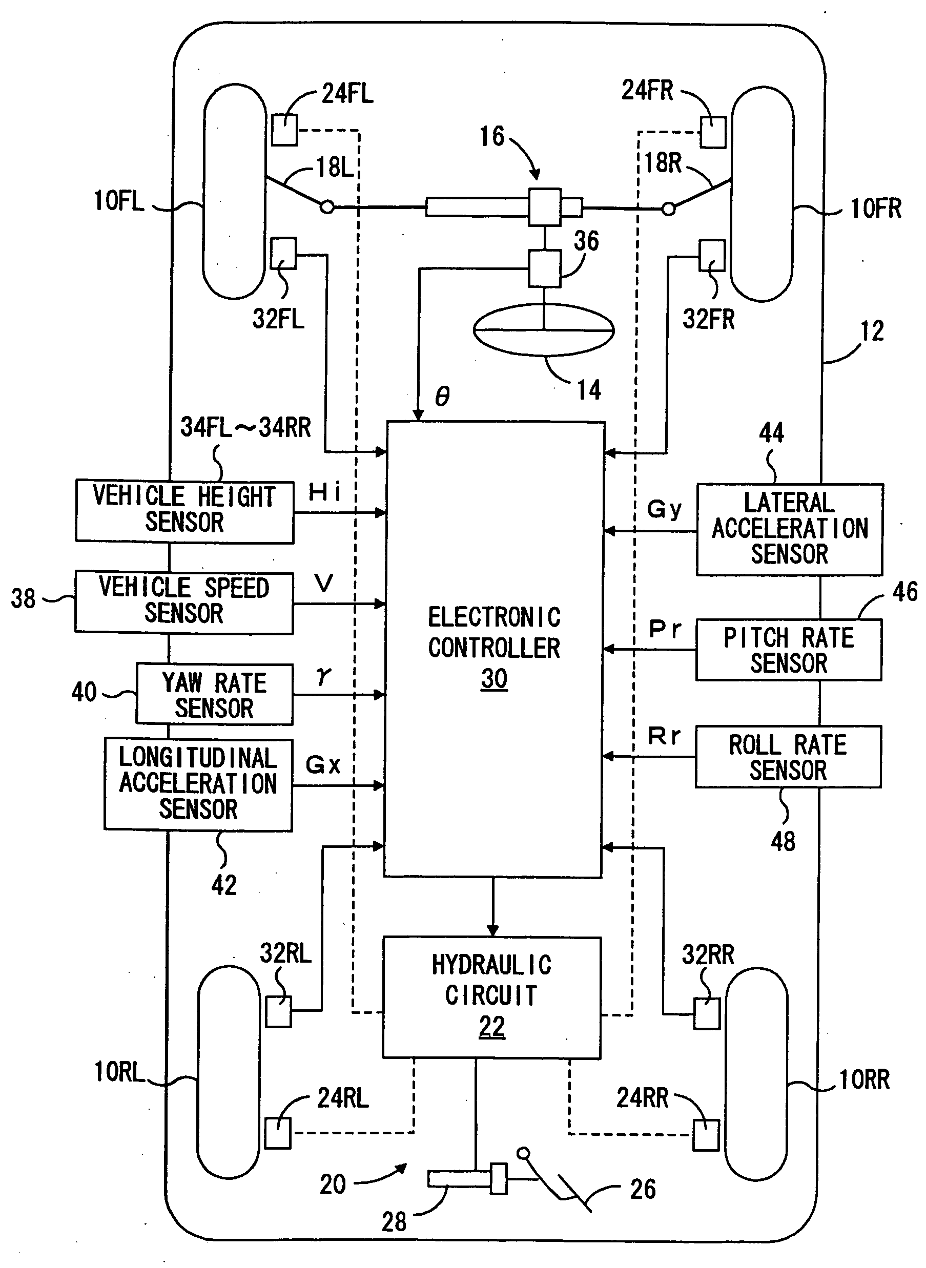
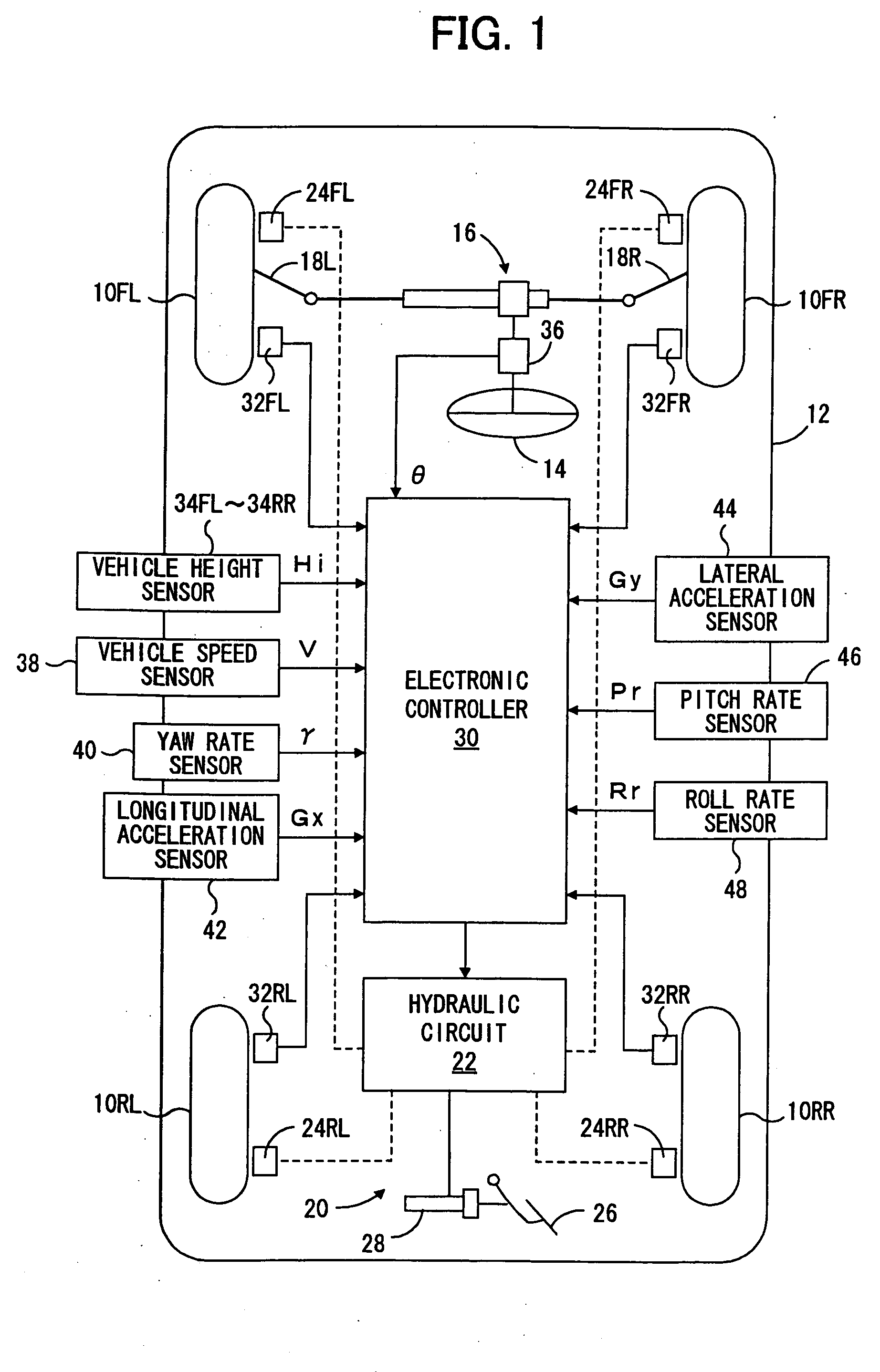
FIG. 1 diagrammatically shows a four-wheel vehicle incorporating a vehicle behavior control device according to the present invention. The vehicle includes a vehicle body 12, front right wheel 10FR, front left wheel 10FL, rear right wheel 10RR and rear left wheel 10RL supporting the vehicle body 12 via the respective suspension means (not shown in the figure). The front right and front left wheels 10FR and 10FL are steered by a rack-and-pinion type power steering apparatus 16 according to a rotation of a steering wheel 14 by a driver via a pair of tie rods 18R and 18L. As usual, the vehicle is also provided with an engine adapted to output a driving torque according to a throttle valve opening in response to the depression of an acceleration pedal by the driver, and a transmission providing a driving force to the wheels through a differential gear system (not shown).

A brake system generally designated by 20 includes a hydraulic circuit 22, a brake pedal 26 adapted ...


PUM


Abstract

The inventive vehicle behavior control device employs a novel control strategy, suppressing deterioration of a vehicle behavior which would be induced during control processes, and being useful especially for correcting or inhibiting excessive deterioration of a vehicle behavior such as when a risk of rolling-over is detected. The device firstly judges if a possibility of rolling-over of the vehicle is high and calculates a target braking control amount for reducing the possibility of rolling-over in accordance with the result of the judgment of a possibility of rolling-over of the vehicle, where the target control amount when the possibility of rolling-over is high is set higher than when the possibility is low. Then, under control of the inventive control device, wheel braking force is controlled based upon the target braking control amount. After the starting of control of the wheel braking force, however, increasing and decreasing gradients of wheel braking force is restricted when a high possibility of rolling-over is judged.

Description

BACKGROUND OF THE INVENTION 1. Field of the Invention The present invention relates to a device for controlling a behavior or an attitude of a vehicle such as an automobile, and more specifically, to such a device modified against a highly unstable behavior such as when a risk of rolling over a vehicle body is detected. 2. Description of Prior Art A modern vehicle employs a system for controlling a behavior or an attitude of a running vehicle body. In such a vehicle, for instance, a braking system, in which braking force on each wheel can be independently increased and decreased, adjusts braking and / or traction force on wheels to modulate yaw moment and centripetal force on the vehicle body for maintaining a dynamical stability of the running vehicle under the control of an electronic control device. In accordance with such a system, which is often called “VSC (Vehicle Stability Control)” system, spinning (oversteering) and / or drifting-out (understeering), caused by excessive ya...

Claims


Application Information

Patent Timeline
IPC IPC(8): B60R16/02B60R21/00B60T7/12B60T8/172B60T8/1755B60T8/24B60T8/58B60W40/10
CPCB60G2800/0124B60G2800/922B60T2230/03B60T8/17558B60T8/243B60T8/17554B60T8/58B60T7/12
Inventor UENO, HIROSHIKOBAYASHI, YASUSHIYAMADA, NORITAKAMIWA, YUKIHISA
Owner TOYOTA JIDOSHA KK
Learn More